
Related Manuals for Julabo Magio MX


Summary of Contents for Julabo Magio MX
- Page 1 Bridge-mounted, bath and heating circulators Original operating manual 1.950.1750.us.V03 11/2021...
- Page 2 Legal JULABO USA, Inc. 884 Marcon Boulevard Allentown, PA 18109 Phone: +1(610) 231-0250 Fax.: +1(610) 231-0260 Info@julabo.us www.julabo.us The content of this operating manual is protected by copyright. Information, including texts, images, and other contents may not be reproduced, distributed, transmitted, stored or otherwise used in any form without prior explicit written consent.
-
Page 3: Table Of Contents
Contents Foreword .................... 8 About this manual ................9 Accessories ..................9 Warnings ..................9 Symbols used ................10 Intended use ..................11 Safety ....................12 General Safety Instructions for the operating company....12 General Safety Instructions for the operator ......... 12 General Safety instructions for device operation ...... - Page 4 5.9.2 Menu Determine thermodynamics........... 29 5.9.3 Menu Connect unit ..............29 5.9.4 Menu Use programmer ............30 5.9.5 Record data menu ..............30 5.9.6 Install unit menu ..............30 5.9.7 Settings menu ................. 30 5.9.8 Unit account menu ..............31 5.9.9 Service menu ................
- Page 5 Operation ..................51 Switch on the unit ................. 51 Switch off the unit ................. 51 Basic settings ................51 8.3.1 Set language ................51 8.3.2 Change language to English ........... 52 8.3.3 Set date and time ..............52 8.3.4 Activate autostart function ............52 8.3.5 Set physical units ..............
- Page 6 8.7.7 Set up actuating variable ............65 8.7.8 Request device status ............. 66 Watchdog function ................ 66 Working with the programmer ............67 8.9.1 Setting the timer ..............67 8.9.2 Creating and editing a temperature control profile ....68 8.9.3 Import temperature control profile ...........
- Page 7 11.1 Interface commands ..............84 11.1.1 IN commands ................85 11.1.2 OUT commands ..............88 11.1.3 Status commands ..............91 11.1.4 Status messages ..............91 11.2 Alarms and Warnings ..............92 11.3 Modbus TCP/IP register ............... 95 11.3.1 Data type ................. 95 11.3.2 Feedback on invalid entries.............
-
Page 8: Foreword
Foreword Congratulations! You have made an excellent choice. JULABO would like to thank you for the trust you have placed in our company and products. This operating manual will help you become acquainted with the use of our units. Read the operating manual carefully. Keep the operating manual handy at... -
Page 9: About This Manual
Read the Safety section of this manual before using the equipment for the first time. Accessories JULABO offers a wide range of accessories for the devices. Accessories are not described in this manual. The complete range of accessories for the devices described in this manual can be found on our website www.julabo.com. -
Page 10: Symbols Used
About this manual DANGER This signal word designates a danger with a high level of risk which, if it not prevented, will result in death or serious injuries. NOTE This signal word designates a possibly harmful situation. If it is not avoided, the system or objects in its vicinity may be damaged. -
Page 11: Intended Use
This section defines the purpose of the unit so that the operator can operate the unit safely and avoid misuse. JULABO circulators are laboratory devices that are designed for temperature control applications with liquid media in a bath tank or with a cooling machine. -
Page 12: Safety
Safety Safety General Safety Instructions for the operating company This section outlines the General Safety Instructions that must be observed by the operator to ensure safe operation. • The operator is responsible for the qualifications of its operating personnel. • The operator must ensure that the operating personnel has been instructed in use of the device. -
Page 13: General Safety Instructions For Device Operation
Safety • Do not remove safety symbols • Have all service and repair work carried out by authorized specialists only • Protect device from dirt • Protect device direct UV radiation General Safety instructions for device operation This section lists the General Safety Instructions for device operation. These Safety Instructions must be followed to ensure safe operation. -
Page 14: Safety Symbols
Safety Safety symbols There are safety symbols included with the device, which should be attached to the device before initial operation. Safety Description symbols Warning of a danger zone. Note operating manual Warning about hot surface Warning of cold surface Read operating manual before switching on Safety function Technical protective devices provide for safe operation. - Page 15 Safety Overheating protection The overheating protection prevents overheating of the heater. • The protective mechanism is triggered when the device recognizes a temperature difference of more than 20 K between the working temperature sensor and the safety temperature sensor. Am error message appears on the display.
-
Page 16: Product Description
Produc t overview Product overview Circulators can be combined with various baths and cooling machines. Bridge mounted circulator Heating circulator MAGIO MX-Z: Circulator with Circulator with closed stainless steel extendable telescopic bridge for bath tank. mounting on open bath tanks... -
Page 17: Operating And Functional Elements
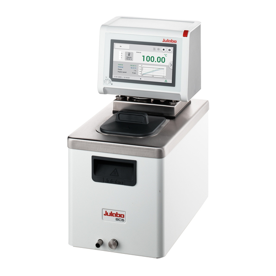
Product description Operating and functional elements The following figure shows the operating and functional elements and their position on the unit. Control and function elements Mains switch Touchscreen High temperature cut-off setting Mounting screws Ethernet interface USB interface Type A USB interface Type B Stakei outlet, secured Mains fuse... -
Page 18: Interfaces
Product description CAN plug for connection with a cooling machine Cover for electronic module with analogue connections (accessories) Supply pump connection Runback pump connection Interfaces 5.4.1 Connection of Pt100 temperature sensor The plug ext. Pt100 is used to connect an external Pt100 temperature sensor. The following section describes the wiring of the plug as well as the connection cable of the temperature sensor. -
Page 19: Stakei Output
Product description 5.4.2 Stakei output The Stakei output is a control output that can be adjusted to solenoid valves with various tasks via the operating menu. The desired function is set and activated in the operating menu. The Stakei output can be assigned the following functions: •... -
Page 20: Rs232/Rs485 Interface
Product description 5.4.3 RS232/RS485 interface The RS232 or RS485 interface is a 9-way D-sub socket for connecting the device to a PC. RS232/RS485 socket RS232 interface pin assignment Pin 2 RxD receive data Pin 7 RTS request to send Pin 3 TxD transmit data Pin 8 CTS clear to send... -
Page 21: Ethernet Interface
Product description 5.4.4 Ethernet interface The device can be connected to a network or directly connected to a PC using the Ethernet interface. Analog interfaces (accessories) The module with analogue interfaces can be ordered as an accessory. Slot with analogue connections Alarm output REG/EPROG plug Standby input... -
Page 22: Reg/Eprog Socket
Product description In the <Analog module> menu, a defined state can be selected as the trigger for the <Alarm output>. When the respective state is reached, pins 2 and 3 are connected: • Standby • Alarm • Alarm + Standby When the respective state is reached, pins 1 and 2 are connected: •... -
Page 23: Standby Input
Product description 5.5.3 Standby input With the standby socket the device can be put in standby mode using an external signal transmitter. [1] External contact, e.g. switch [2] Pin 3 [3] Pin 1 [4] Pin 2 Standby socket diagram... -
Page 24: Operating Interface
Product description Operating interface The device is operated by touchscreen. When it is switched on, the display shows the home screen. Sideways swiping or pressing the side arrows allows selection between three different home screen presentations. Home screen [1] Softkey [Settings] accesses the <Main menu> [2] Internal/external control display [3] Display of current internal/external temperature, display off in standby mode... -
Page 25: Softkeys And Status Icons
Product description 5.6.1 Softkeys and status icons This section describes the softkeys and status icons found on the operating interface. Softkey Function With the softkey [Start] a temperature control application is started With the softkey [Stop] a temperature control application is stopped With the softkey [Settings] the <Main menu>... -
Page 26: Explanation Of Abbreviated Terms
Product description 5.6.2 Explanation of abbreviated terms The following abbreviations are used on the Home screen: Abbreviations Explanation Setpoint temperature Overtemperature warning Over. warn. Subtemperature warning Sub. warn. Overtemperature alarm Over. alarm Subtemperature alarm Sub. alarm High temperature cut-off Protect. Maximum setpoint temperature Set max. -
Page 27: Alarm Messages
Product description Alarm messages Errors or disturbances are indicated on the Home screen by alarm messages or warnings. Tapping the message displays a help text. Important error code descriptions can be found in the appendix. If you are unable to rectify a fault, contact Technical Service. -
Page 28: Operator Messages
Product description Operator Messages Operator messages are informal messages that inform the operator about status changes of the device. Operator message display Operator messages are shown on a blue background. They provide information about the operating states of individual units on the Home screen. Status messages from a connected cooling machine are also displayed as operator messages. -
Page 29: Adjust Safety Menu
Product description 5.9.1 Adjust safety menu In the menu <Adjust safety> limit values are set to define a range for safe process flow. • Enabling/disabling autostart • Setting pump mode • Setpoint limits: Setting of the upper and lower limits for temperature setpoint as well as the maximum pump performance •... -
Page 30: Menu Use Programmer
Product description 5.9.4 Menu Use programmer The menu <Use programmer> is used to program temperature curves, which can be called up according to definable rules. • Activate programmer: Set the start time, setpoint, final state, duration and number of runs of a temperature control application. Programming profile series •... -
Page 31: Unit Account Menu
Set inactivity timer • Access rights for basic and advanced users 5.9.9 Service menu The menu <Service> is reserved for JULABO service technicians and password protected. 5.9.10 Menu About The menu <About> provides information about the installed software status. •... -
Page 32: Technical Data
Product description 5.10 Technical data This section outlines the technical data of the device. The materials of parts that come into contact with the medium are also listed. The technical data relate to the nominal voltage and nominal frequency as well as an ambient temperature of 20°C. - Page 33 Product description MAGIO MX Temperature control application Working temperature range °C +20 … +300 Temperature stability °C ±0.01 Temperature resolution °C 0.01 Temperature control Temperature setting Digital Absolute Temperature Calibration 10-point adjustment (ATC) Pump Pump capacity* Volume flow l/min Supply pressure 0.24...
-
Page 34: Material Of Parts That Come Into Contact With The Medium
Product description 5.10.1 Material of parts that come into contact with the medium The table lists parts that could come into contact with the bath fluid as well as the material that the parts are made of. This data can be used to check the compatibility of the parts with the bath fluid used. -
Page 35: Bath Fluids
Recommended bath fluids and further information can be found on our website NOTE No liability accepted for usage of bath fluids that are not suitable! Unsuitable bath fluids that are not approved by JULABO can damage the water bath. • Use bath fluids that are recommended by JULABO •... -
Page 36: Hoses
Product description 5.10.3 Hoses Hoses for connection of an external system must suit the working temperature range and the respective temperature control application. Hoses for every area of application can be found on our website. Hoses must meet the following requirements: •... -
Page 37: Transport And Installation
Transport and installation Transport and installation This section describes how to transport the unit safely. Transporting the device A circulator can be transported with the closed bath when mounted. CAUTION Risk of crushing by falling device! A device that is not secured appropriately can fall down during improper transport and cause crushing injuries. -
Page 38: Install The Device At The Operating Location
Transport and installation Install the device at the operating location This section describes how the device is set up at the installation location. The device has been transported to the operation location. The size and infrastructure of the operation location are suitable for device operation. -
Page 39: Initial Operation
Initial operation Initial operation Commissioning is carried out in various steps, depending on how the device is to be used. Mounting the circulator Bridge Mounted Circulator 7.1.1 Mount bridge mounted circulator With the extendable telescopic bridge, the circulator can be mounted on open bath tanks with a width of 33 cm to 68 cm. -
Page 40: Mount Heating Or Refrigerated Circulator
Initial operation 7.1.2 Mount heating or refrigerated circulator In the case of a heating circulator or a refrigerated circulator, the circulator is mounted on the closed bath or on cooling machine. If the circulator is disassembled, e.g. due to a change of device or for service purposes, it can then be easily reassembled with the connecting box. -
Page 41: Connect The Device To The Power Supply
Initial operation Connect the device to the power supply 7.2.1 Connect bridge mounted or heating circulator This section describes how the circulator is connected as a bridge mounted circulator or heating circulator. The circulator is mounted as a bridge mounted or heating circulator. ... -
Page 42: Connecting An External System
Initial operation Connecting an external system The device is designed for tempering external, closed loop systems. An external system is connected to the unit’s pump connections. CAUTION Risk of burns due to damaged temperature control hoses! Hot bath fluid can escape from damaged temperature control hoses and cause serious burns when it comes into contact with skin. -
Page 43: Connect An External System With Screw Connections
Initial operation NOTE Overflowing bath fluid due to externally connected systems! If the externally connected system is higher than the temperature control system, bath fluid can flow back and overflow when switched off. • Position the connected external system on the same level or lower than the temperature control system •... -
Page 44: Connect An External System With Barbed Fittings
Initial operation 3. Screw the hoses onto the pump connectors by hand. Pay attention to the supply and runback position. 4. Screw on the pump connections carefully with a maximum of 3 Nm torque. The external system is connected. ... -
Page 45: Switch On The Device And Set The Language
Initial operation 4. Mount the barbed fittings with the union nuts on the pump connections. 5. Carefully tighten the union nuts with a maximum of 3 Nm torque. 6. Attach the hoses of the external system on the barbed fittings. ... -
Page 46: Set High Temperature Safety Function
Initial operation Set high temperature safety function Before each new temperature application, the temperature must be set for the tank and internal reservoir high temperature cut-off. Set a value that is at least 25 K below the flash point of the bath fluid being used. The surface temperature of the bath fluid must not exceed the flash point at any time. -
Page 47: Fill Device
Initial operation Fill device This section describes how the device should be filled with bath fluid during initial operation. Specifications for filling volume can be found in the technical data. The drain valve is closed. The device is switched off. 1. -
Page 48: Set Limit Values
Initial operation Set limit values 7.7.1 Set temperature warning limits A warning limit and an alarm limit can be set for low temperature and high temperature. The warning limit values should be within the alarm limit values. If the respective temperature limit is exceeded, the device generates an alarm or warning message. -
Page 49: Adjusting Actual Value Limits
Initial operation 7.7.3 Adjusting actual value limits The actual value limits “internal minimum” and “internal maximum” are effective in the external control operating mode. They define limits for the expected temperature in the internal bath. The temperature controller cannot exceed these limit values. Under certain circumstances, the external setpoint will not be reached. -
Page 50: Setting Band Limit
Initial operation In order to gently control the temperature of a sample in an external system, or to protect a glass reactor from thermal stress, for example, maximum permissible temperature differences can be specified for the heating phase and the cooling phase. 7.7.5 Setting band limit The upper and lower band limit is defined in °K. -
Page 51: Operation
Operation Operation Switch on the unit This section describes how to switch on the device. The device is connected and ready for operation. 1. Switch the device on at the mains switch. The software boots and starts the device. The display shows the device name, voltage version and software version. -
Page 52: Change Language To English
Operation 8.3.2 Change language to English A special function makes it easy to change the user interface language to English at any time. The device is switched on. 1. Call up the <Main menu>. 2. Tap the <Main menu> text field on the left menu item for more than 3 seconds. -
Page 53: Set Physical Units
Operation 8.3.5 Set physical units The physical units for temperature, pressure and flow can be set in the menu. The device is switched on. 1. Call up the <Main menu>. 2. Call up the submenu <Settings>. 3. Set the desired units for temperature, pressure and flow. ... -
Page 54: Defining User-Dependent Settings
Operation 6. First think of a new password and make a note of it. Note: Entering a new password will overwrite the previous password. It can no longer be restored! This also applies to the password preset ex works. 7. -
Page 55: Log In User
Operation 8.4.4 Log in user Logging in a user activates the access rights assigned to their user group. The device is switched on. 1. Call up the <Main menu>. 2. In the submenu <Unit account> press the [Log in] button. ... -
Page 56: Lock The Device
Operation 8.4.6 Lock the device A logged-in user can lock the device to prevent unwanted interventions. Active temperature control application is not interrupted. A locked device cannot be operated, it must first be unlocked by the last user or an administrator. ... -
Page 57: Record Data
Operation Factory setting for the administrator password: 000000. 4. Press the <Reset> button. 5. Acknowledge the confirmation prompt with [OK]. All unit account settings are reset to factory settings. Record data 8.5.1 Record measurement data Measurement data for an ongoing temperature control application can also be recorded onto a USB stick at the same time. -
Page 58: Displaying Alarm Memory
Operation 4. Scroll down the display to Blackbox and press the [File] button to change the displayed filename if required. 5. Press the button [Save]. The blackbox data is saved onto the USB stick as a .txt file. 8.5.3 Displaying alarm memory Alarm messages are stored with date, time, alarm code and unit identifier. -
Page 59: Thermodynamics
Operation Thermodynamics 8.6.1 Control parameter The device works with a PID control. Experience has shown that the control parameters set ex works achieve an optimal temperature sequence in the sample. The internal and external control parameters can be adjusted in the submenu <Control performance>. -
Page 60: Optimizing Temperature Curves
Operation 8.6.2 Optimizing temperature curves The temperature sequence shown on the display provides information about how individual control parameters can be optimized to achieve a better result. Optimal temperature sequence, temperature quickly reaches the setpoint without overshooting, and keeps the setpoint. Symptom: Temperature sequence slowly approaches the setpoint and doesn’t quite reach it. -
Page 61: Adjust Controller
Operation 8.6.3 Adjust controller In the menu <Adjust controller> the individual control parameters for internal and external control can be set. The device is switched on. 1. Call up the <Main menu>. 2. Call up the submenu <Determine thermodynamics> and the menu option <Adjust controller>. -
Page 62: Remote Control Device
1. Connect the device (USB plug type B) to the computer with a commercially available USB cable. 2. Download the suitable USB driver from the download area of the website www.julabo.com. Depending on the operating system used by the connected computer, it may be necessary to install the USB driver. -
Page 63: Remote Control Device Using Rs232 Interface
Operation 4. Set the interface parameters if they differ from the factory settings. If parity is "None," the number of data bits is set to 8. The interface parameters are set. 8.7.3 Remote control device using RS232 interface The device can be remote-controlled via the RS232 interface. -
Page 64: Set Eprog Input
Operation 7. Start the terminal program on the computer. 8. Enter the interface parameters into the terminal program. 9. Use the terminal program to select the COM port of the circulators or the connected adapter, and establish a connection. Remote control via the RS485 serial interface is activated. You can now remote control the circulators with interface commands via the terminal program. -
Page 65: Set External Setpoint Values
Operation 8.7.6 Set external setpoint values By default the setpoint is adjusted on the device or by the programmer. In addition to this, the device offers the ability to externally specify the setpoint using the analog REG/EPROG plug or an external Pt100 temperature sensor. ... -
Page 66: Request Device Status
Operation 8.7.8 Request device status The current device status can be queried via an interface command. The device is connected to a PC via an interface. 1. Enter the command "status“ in the terminal program and press [Enter]. The device responds with a status message. If an alarm or warning is pending, the device sends the respective alarm or warning message to the status query. -
Page 67: Working With The Programmer
Operation Working with the programmer Temperature control profiles are defined temperature profiles with a setpoint temperature as well as a predefined temperature control duration or a predefined gradient. The programmer calculates a temperature ramp from these programmed values. The programmer can start these temperature control profiles directly or with a time delay. -
Page 68: Creating And Editing A Temperature Control Profile
Operation 5. In the [Final state] field, select how the device should behave after the timer expires. 6. Enable the [Activate] field to start the timer. The timer is programmed and active. The set duration starts to elapse once the setpoint temperature is reached. -
Page 69: Import Temperature Control Profile
Operation 8.9.3 Import temperature control profile Temperature control profiles can be imported from another device via a USB stick. The device is switched on. 1. Insert the USB stick with a temperature control profile to be imported into the USB socket. 2. -
Page 70: Profile Series Setup
Operation 2. From the submenu <Use programmer>/<Programmer> call up the menu option <Manage profile>. 3. Select a temperature control profile. 4. Press the <Save> button. 5. Acknowledge the confirmation prompt. The temperature control profile will be deleted. Once all steps are removed, the [Add step] softkey remains in the deleted profile. -
Page 71: Activate Programmer
Operation 8.9.7 Activate programmer The programmer is started with a selected profile and runs through the profile according to the specifications. The device is switched on. The programmer is deactivated. 1. Call up the <Main menu>. 2. Call up the submenu <Use programmer> then the menu option <Activate programmer>. -
Page 72: Configure Signal Outputs
Operation 8.10 Configure signal outputs 8.10.1 Set up Stakei outlet A solenoid valve connected to the Stakei output can be assigned various functions depending on the application. The device is switched on. A solenoid valve is connected to the Stakei output. 1. -
Page 73: Configure Alarm Outputs
Operation 8.10.3 Configure alarm outputs This section describes how the alarm output is configured. The device is switched on. The electronics module with analog connections is mounted. 1. Call up the <Main menu>. 2.Call up the submenu <Connect unit>.2 3.From the submenu <Interfaces>, select the menu option <Analog module>.3 4. -
Page 74: Adjusting The Temperature Sensor (Atc)
Operation 8.12 Adjusting the temperature sensor (ATC) For physical reasons, there can be a temperature difference in the bath tank between the temperature sensor and a defined, more remote point within the bath fluid volume. As a result, the measured temperature deviates slightly from the actual bath temperature. -
Page 75: Adjust The Internal Temperature Sensor - Multi-Point Calibration
Operation 10. Enter the required value and confirm your entry. The correction value is active immediately. The internal temperature sensor is adjusted with a correction point. 8.12.2 Adjust the internal temperature sensor - multi-point calibration This section describes how to adjust the internal temperature sensor of the device with multiple correction points. -
Page 76: Adjust External Temperature Sensor
Operation 8.12.3 Adjust external temperature sensor Measurable temperature differences can also occur in a connected application. As with the internal temperature sensor, adjustment of the external temperature sensor can improve accuracy of the temperature control application. The device is switched on. ... -
Page 77: Maintenance
1. Check the safety signs on the device for legibility and completeness. 2. Replace defective or missing safety markings. Safety signs can be reordered from JULABO. The safety signs on the device have been checked. Check the functionality of high temperature cut-off This section describes how you can test that the high temperature safety function is operational. -
Page 78: Test The Low Liquid Level Safety Function
If the power cord needs to be replaced, ensure that the new one is at least dimensioned for the device power requirements. Insufficiently dimensioned power cords must not be used. See type plate for mains voltage and current value. We recommend only using original JULABO spare parts. -
Page 79: Emptying
Maintenance Emptying The device must be completely drained if it is to be sent in for technical service or is to be properly disposed of. In general, the device should be completely emptied before longer shutdowns or when there is a change to the external application. CAUTION Risk of burns due to hot bath fluid! Bath fluid can become very hot during a temperature control process. -
Page 80: Device Storage
The device is protected and can be safely stored there. It can be put into operation again as needed. Technical Service If the unit shows faults you cannot resolve, please contact our Technical Service. JULABO Technical Service Tel.: +1(610) 231-0250 Option 3 Fax: +1(610) 231-260 Email: Service@julabo.us... -
Page 81: Warranty
Warranty The following Warranty Provisions shall apply to products sold in North America by Julabo (“Seller”) to the entity shown as buyer (“Buyer”) on Seller’s invoice. Initial Warranty Upon Seller’s receipt of payment in full for the products and subject to Buyer’s... - Page 82 Maintenance be extended. All repairs or replacements performed by Seller pursuant to these Warranty Provisions shall be performed at one of the Seller’s facility in Allentown, Pennsylvania, U.S.A. or at the facility of an authorized representative of Seller, which location shall be determined by Seller in its sole discretion; provided, however, that Seller may, in its sole discretion perform such repairs or replacements at Buyer’s facility in which case Buyer shall pay Seller’s travel, living and related expenses incurred by Seller in performing the repairs or...
-
Page 83: Disposal
The same exclusions that apply to the regular warranty also apply to OBF classification. For example, JULABO will not be liable for transport damage, damage inflicted by the customer or any other party, or defects arising from improper installation or usage. -
Page 84: Appendix
Appendix 11 Appendix 11.1 Interface commands Interface commands allow the device to be remote controlled. Parameters can be retrieved and the current status can be queried. To do this, the device must be connected to the master computer via a digital interface. Interface commands are entered using a terminal program. -
Page 85: In Commands
Appendix 11.1.1 IN commands IN commands retrieve device parameters. Process values System response in_pv_00 Actual value in_pv_01 Current variable (%) In_pv_02 Current temperature of the external Pt100 temperature sensor in_pv_03 Current temperature of the temperature safety sensor in_pv_04 Current setting of the high temperature safety function in_pv_06 Current pressure. - Page 86 Appendix Device modes System response in_mode_01 Return value 0. The value 0 stands for the control temperature setpoint as only one temperature setpoint can be set (downward compatibility for older devices) in_mode_02 Selftune: 0 = Selftune disabled 2 = Selftune Enabled in_mode_03 Operating mode setting for the EPROG input: 0 = 0…10 V...
- Page 87 Appendix in_par_12 Set control parameter Tv of the cascade-controller in_par_13 Set maximum permissible internal temperature InternMax in cascade temperature control in_par_14 Set minimum permissible internal temperature InternMin for cascade temperature control in_par_15 Set band limit upper in cascade temperature control in_par_16 Set band limit lower in cascade temperature control Auxiliary parameters...
-
Page 88: Out Commands
Appendix 11.1.2 OUT commands OUT commands set device parameters. Remote control mode must be active. Parameter settings Parameter Setting out_sp_00 xxx.xx Setting of the setpoint for temperature control out_sp_03 xxx.xx Setting of the high temperature out_sp_04 xxx.xx Setting of the low temperature out_sp_06 xxx.xx Setpoint temperature setting via watchdog function... - Page 89 Appendix 0 = Internal control 1 = External control out_mode_05 Start/stop command of the device in remote control mode: 0 = Stop tempering 1 = Start tempering out_mode_08 Setting of the internal control dynamic: 0 = non-periodic 1 = Standard out_mode_11 Actuating variable source: 0 = Thermostat...
- Page 90 Appendix Auxiliary Parameter Setting parameters out_hil_00 -xxx Setting of the actuating variable limit for cooling capacity (0-100%) out_hil_01 Setting of the actuating variable limit for heating capacity (0-100%) ATC OUT command Parameter Setting ATC:INT:STATUS 1 ... 10 Sets the number of correction points used for internal adjustment.
-
Page 91: Status Commands
Appendix 11.1.3 Status commands Status commands are used to query the current status of the device. Status commands System response version Current firmware version status Return of status, error, warning, alarm 11.1.4 Status messages Possible status messages from the device for a status query. Status message Explanation 00 MANUAL STOP... -
Page 92: Alarms And Warnings
Appendix 11.2 Alarms and Warnings If the device is connected to a network and remotely controlled, a status query via interface command will lead to any alarms or warnings that are present being output as a string. • The maximum output string length for alarms and warnings is 22 characters •... - Page 93 Appendix Error code Description Solution The line of the high temperature • Contact technical service. protection sensor has short circuited or been interrupted. The setpoint value is set to external • Check whether an external temperature sensor, but no signal is temperature sensor is connected or available.
- Page 94 Appendix Error code Description Solution -144 The set temperature limit for • Decrease temperature limit of subtemperature alarm was exceeded. subtemperature alarm or increase temperature setpoint. -503 External setpoint value is set via • Connect analog module or deactivate EPROG, but no analog module is external setpoint specification using connected.
-
Page 95: Modbus Tcp/Ip Register
Appendix Error code Description Solution • Check hose cross-section of connection to application • Check connection to application is clear • Check bath fluid for specification/suitability 11.3 Modbus TCP/IP register 11.3.1 Data type The Modbus protocol uses 16-bit registers for data transmission. Data that use more than 16 bits must be divided into several registers. -
Page 96: Feedback On Invalid Entries
Appendix 11.3.2 Feedback on invalid entries If the device receives an invalid data packet, it responds with an exception response. The following exceptions are recognized by the device. Code Name Explanation Illegal function The received function code is not supported by the device. -
Page 97: Holding Registers
Appendix 11.3.4 Holding registers Register Protocol Data Explanation Adjustable range address address type 40001 ushort Start/stop the device 0: Device is in standby 1: Device is started 40002 ushort Type of actuating variable 0: Controller 1: Digital 2: EPROG 40003- float Setpoint temperature min. - Page 98 Appendix 40022- 21-22 float P-proportion of the 0.1 … 99.9 K 40023 subordinate controller 40024- 23-24 float CoSpeed control 0.0 … 5.0 40025 parameter of the external controller Controller limitations 40041 short Maximum desired cooling -100 ... 0 capacity 40042 short Maximum desired heating 0 ...
-
Page 99: Input Register
Appendix 40102 ushort Month 40103 ushort 40104 ushort Hour 40105 ushort Minutes 40106 ushort Second 11.3.5 Input register Register Protocol Data type Explanation Value range address address 30001- uint Firmware version Byte1: Major 30002 Byte2: Minor Byte3: Build Byte4: Revision 30004- uint Barcode...
Need help?
Do you have a question about the Magio MX and is the answer not in the manual?
Questions and answers