Table of Contents
Advertisement
WIRELESS WIND SPEED
Installation and Operation Manual
Ref: MLF feb. 2020
Wylie Systems
(Rayco Technology Group)
201 Prospect Avenue
Suite 106 - Box 159
Hagerstown, MD 21742
USA
Tel: +1 888-252-1957
Fax: +1 (418) 266-6610
R180
INDICATOR
Rayco Electronic Systems
(Rayco Technology Group)
2440 Dalton Avenue
Ste-Foy, Qc
CANADA
G1P 3X1
Tel: +1 (418) 266-6600
Fax: +1 (418) 266-6610
Copyright © 2020
RaycoWylie Systems
All Rights Reserved.
55M0180GSE00 Rev. E
Wylie Systems
(Rayco Technology Group)
Drury Lane
St-Leonards on Sea, East Sussex
ENGLAND
TN38 9BA
Tel: +44 (0) 1424-421235
Fax: +44 (0) 1424-433760
Advertisement
Table of Contents

Subscribe to Our Youtube Channel
Related Manuals for RaycoWylie R180


Summary of Contents for RaycoWylie R180
- Page 1 55M0180GSE00 Rev. E R180 WIRELESS WIND SPEED INDICATOR Installation and Operation Manual Ref: MLF feb. 2020 Wylie Systems Rayco Electronic Systems Wylie Systems (Rayco Technology Group) (Rayco Technology Group) (Rayco Technology Group) 201 Prospect Avenue 2440 Dalton Avenue Drury Lane...
- Page 5 RaycoWylie Systems. The R180 WindSpeed Indicator is to be regarded only as an aid to the operator. This system must never be used, under any circumstances, as a substitute for the good judgment of a crane operator when carrying out approved crane-operating procedures.
- Page 7 MINOR OR MODERATE INJURY. IT MAY ALSO BE USED TO ALERT AGAINST UNSAFE PRACTICES. IMPORTANT: INDICATES A SITUATION THAT MAY CAUSE MACHINE DAMAGE IF NOT CORRECTLY FOLLOWED. NOTE: PROVIDES INFORMATION THAT MAY BE OF SPECIAL INTEREST. R180 Wireless Wind Speed Indicator Installation and Operation Manual...
-
Page 9: Table Of Contents
24 4.1.2- R180 current version page 24 4.2- Programming the ID Number page 25 4.3- Technical Drawings page 28 4.3.1- R180 legacy version page 28 4.3.2- R180 current version page 30 R180 Wireless Wind Speed Indicator Installation and Operation Manual... -
Page 10: 1- General Description Of The System
GENERAL DESCRIPTION OF THE SYSTEM 1.1 Introduction The Wireless Wind Speed Indicator (R180) is designed as an aid to the crane operator. It eliminates guesswork by measuring and clearly indicating the wind speed to the crane operator. The R180 has a user adjustable maximum wind speed limit. -
Page 11: Component Description
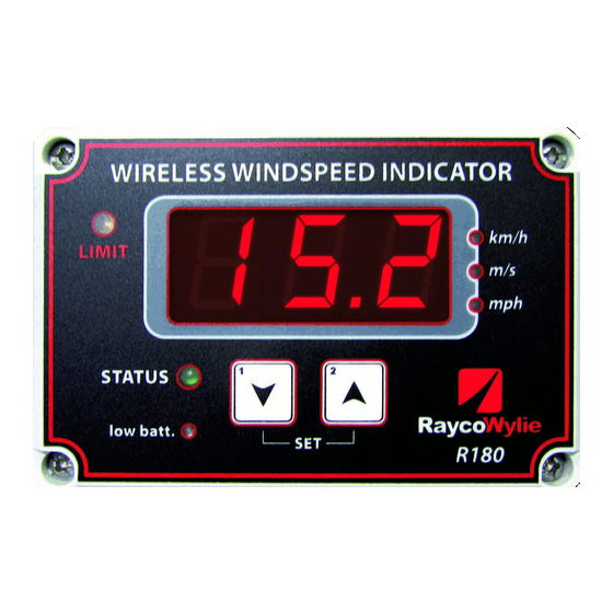
These modes will be described more in detail in the operating section of this manual. ACTUAL WIND SPEED READING LIMIT LIGHT UNITS LIGHTS RECEIVING STATUS LIGHT LOW BATTERY DOWN LIGHT BUTTON BUTTON Fig 1: R180 Display box R180 Wireless Wind Speed Indicator Installation and Operation Manual... -
Page 12: 2- Wireless Wind Speed Sensor
55M0180GSE00-E 1.3.2 Wireless Wind Speed Sensor There are two different versions of the R180, refers to the following pictures to determine the version you own. The legacy version (33M0098) WIND CUPS HITCH PIN CLIP TRANSMITTER UNIT MOUNTING BRACKET Fig 2: Legacy version wind speed sensor complete assembly The wind speed sensor is delivered with a mounting bracket that allows the sensor to stay perpendicular to the ground at all boom angles. - Page 13 The transmitter unit contains the battery and the transmitting antenna. The anemometer must be fully exposed to the wind and spin freely at all boom angles R180 Wireless Wind Speed Indicator Installation and Operation Manual...
-
Page 14: 2- Operating Procedure
OPERATING PROCEDURE 2.1 Power On Switch on the electrical supply (ie crane key switch) to the R180 system. During the time the indicator is waiting for a valid radio transmission from the wind speed sensor, the display will show three horizontal lines and the green status... -
Page 15: Units
55M0180GSE00-E 2.2 Units The R180 indicates wind speed in miles per hour (mph), meters per second (m/s) or kilometers per hour (km/h). Current units are indicated by a green light “on” beside the selected unit. To change units press simultaneously the Down and Up button. -
Page 16: 3- Installation And Setup
Use one of the three holes available at the top of the bracket and another one at the bottom of the bracket. Install the display using bolts ¼ (Bolts, Nuts, washer not included). A power and alarm cable is provided with the R180 display. The power supply can be from 10-30 volt DC. Pin #... -
Page 17: Wireless Wind Speed Sensor Installation
3.2 Wireless wind speed sensor installation 3.2.1 Installing and connecting the wind cup (Legacy version only) It could happen that you receive your R180 System with the wind cup disassembled. To assemble the wind cup on the shaft execute the following... - Page 18 4) Slide the rubber hood on the shaft terminals of the wind cups assembly. to protect the terminals. There is no polarity, you can place the wire you want in the terminal of your choice. R180 Wireless Wind Speed Indicator Installation and Operation Manual...
-
Page 19: 2- Battery Paper Tag Removal
2. Remove by hand the paper tag insulation. 3. Replace the cover and screws. Don’t over-tighten 3.2.2.2 R180 current version Simply Remove by hand the “Remove before use” paper tag insulation. R180 Wireless Wind Speed Indicator Installation and Operation Manual... -
Page 20: 3- Installing The Wind Speed Sensor
Fig 6: Wind speed sensor typical mounting position. R180 Wireless Wind Speed Indicator Installation and Operation Manual... - Page 21 Do not weld in proximity of the wind speed sensor or the Display 4. Place the wind speed sensor on the mounting bracket, add washer and secure with the hitch pin clip. R180 Wireless Wind Speed Indicator Installation and Operation Manual...
-
Page 22: 2- R180 Current Version
The wind speed sensor must be installed at the highest point possible of the boom tip in a way that the anemometer is fully exposed to the wind and pivot freely on the mounting bracket at all boom angles. R180 Wireless Wind Speed Indicator Installation and Operation Manual... - Page 23 4. Replace the mounting bracket on the welded clevis pin and tighten the 10mm nut to hold it in place. 5. Place the wind speed sensor on the mounting bracket and secure with the hitch pin clip. R180 Wireless Wind Speed Indicator Installation and Operation Manual...
-
Page 24: 4- Maintenance
55M0180GSE00-E MAINTENANCE 4.1 Battery Replacement Always use a RaycoWylie Systems supplied battery. These are long duration batteries of 3.6 volts that are not available in stores. See the cover of this Fig 9: 3.6V Battery 4.1.1 R180 legacy version 1. Unscrew the four allen screws using HEX key 4 mm in order to remove the cover of the wind speed sensor. -
Page 25: Programming The Id Number
2 digits “HIGH” 2 digits “LOW” part of the ID part of the ID number number 2 digits “HIGH” 2 digits “LOW” part of the ID part of the ID number number R180 Wireless Wind Speed Indicator Installation and Operation Manual... - Page 26 “LOW” part of the ID number. Take note of these four digits. 3. Turn off the power supply of the R180 display. Using a Phillips screwdriver, open the display box of the R180.
- Page 27 9. Put the jumper back at its normal position and switch off the power supply. It’s important to note that the jumper must be put back before to switch off the power. Put the R180 cover back on and switch on the power supply. R180 Wireless Wind Speed Indicator...
-
Page 28: Technical Drawings
Pivot spindle to be welded to side of boom top. This face to be vertical at all times. 4.38" 111.1mm 2.88" 2.53" 73mm 64.3mm R180 Wireless Wind Speed Indicator Installation and Operation Manual... - Page 29 55M0180GSE00-E 4.3.1 R180 legacy version (continued) 10.7" (272mm) minimum swing clearance O 7.5" 190mm 10.17" 258.3mm 2.00" 50.8mm Pendulum 2.00" pivot point 50.8mm 6.00" 152.4mm 6.4" (163mm) minimum swing clearance 4.00" 101.6mm R180 Wireless Wind Speed Indicator Installation and Operation Manual...
-
Page 30: 2- R180 Current Version
55M0180GSE00-E 4.3.2 R180 current version .625" 15.9mm 5.854" 148.7mm 11.358" 288.5mm 7.918" 201.1mm .510" 13mm 8.529" 216.6mm 9.348" 237.4mm 1.130" 28.7mm R180 Wireless Wind Speed Indicator Installation and Operation Manual...
Need help?
Do you have a question about the R180 and is the answer not in the manual?
Questions and answers