RaycoWylie i4000 Instruction Manual
Excavator rated capacity limiter and range limiting system
Hide thumbs
Also See for i4000:
- Instruction manual (72 pages) ,
- Calibration instructions manual (31 pages)
Table of Contents
Advertisement
Quick Links
Excavator Rated Capacity Limiter and Range
Rev: MLF April 2019
Wylie Systems
(Rayco Technology Group)
201 Prospect Avenue
Suite 106 - box 159
Hagerstown, MD 21742
USA
Tel: +1 888-252-1957
Fax: +1 (418) 266-6610
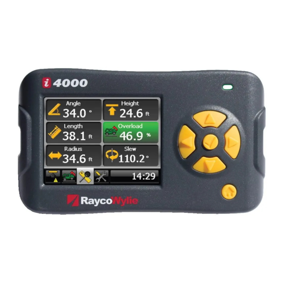
i4000
Limiting System
Instruction Manual
Rayco Electronic Systems
(Rayco Technology Group)
2440 Dalton Avenue
Ste-Foy, Qc
CANADA
G1P 3X1
Tel: (418) 266-6600
Fax: (418) 266-6610
Copyright © 2019
RaycoWylie Systems
All rights reserved.
55M4000UBE00-A
Wylie Systems
(Rayco Technology Group)
Drury Lane
St-Leonards on Sea, East Sussex
ENGLAND
Tel: (+44) 1-424-421235
Fax: (+44) 1-424-433760
TN38 9BA
Advertisement
Table of Contents

Subscribe to Our Youtube Channel
Related Manuals for RaycoWylie i4000


Summary of Contents for RaycoWylie i4000
- Page 1 55M4000UBE00-A i4000 Excavator Rated Capacity Limiter and Range Limiting System Instruction Manual Rev: MLF April 2019 Rayco Electronic Systems Wylie Systems Wylie Systems (Rayco Technology Group) (Rayco Technology Group) (Rayco Technology Group) 2440 Dalton Avenue Drury Lane 201 Prospect Avenue...
-
Page 3: Warning
All procedures herein are based on the use of the system under proper operating of the equipment are strictly forbidden without written approval from RaycoWylie Systems. The i4000 RaycoWylie Systems Excavator Information Center must be regarded only as an aid to the operator. - Page 5 SITUATION WHICH, IF NOT AVOIDED, COULD RESULT IN MINOR OR MODERATE DAMAGES. IT CAN BE USED TO WARN ABOUT UNSAFE PRACTICES. IMPORTANT: INDICATES A SITUATION WHICH COULD DAMAGE THE MACHINERY. NOTE: PROVIDES INFORMATION WHICH CAN BE OF SPECIAL INTEREST. i4000 RCL For Excavator Instruction Manual...
-
Page 7: Table Of Contents
3 1 - GENERAL DESCRIPTION OF THE SYSTEM page 9 Introduction page 9 Operator skill page 9 Usefulness of the i4000 system page 9 Description of the i4000 system page 10 1.4.1 Audible alarm page 11 1.4.2 Visual alarm... - Page 8 56 8 - INSPECTIONS AND MAINTENANCE page 59 Frequent inspections page 59 Periodic inspections page 59 Checking the displayed load page 60 Maintenance page 61 Maintenance procedure page 62 Adjustments and repairs page 63 Instruction Manual i4000 RCL For Excavator...
-
Page 9: General Description Of The System
Please make sure you respect the safety rules currently in force in the country where you are using the i4000 system, in order to reduce the risk of injuries or of damages to the machinery. Please consider each safety directive mentioned in this manual when using the i4000 maintenance. -
Page 10: Description Of The I4000 System
55M4000UBE00-A Description of the i4000 system of the excavator. This version measures the boom cylinder pressure, the boom angle and the stick angle to indicate safe or critical conditions, while performing slew angle to provide some extra information to the operator. All the sensors are linked through a single CAN bus (Controlled Area Network). -
Page 11: Audible Alarm
1.4.2 Visual alarm The i4000 system display has been equipped with a 3-colour warning light to alert alarm when the load reaches the approach alarm’s threshold, that is, 90% of the nominal capacity. -
Page 12: Location And Description Of Typical Components
55M4000UBE00-A Location and description of typical components 1. i4000 display system: It is also the central processing unit (CPU) of the system. Its principal feature is a CAN Bus communication interface and graphical LCD screen. 2. Central I/O interface: This relay interface module is connected to individual external I/O devices to be controlled or monitored by the i4000 system. -
Page 13: Overall Scheme
12-30 VDC Display 10/100 Mbps (Optional) Angle (Split boom) Angle (Boom) Angle (Stick) Slew (33S0047) Capteurs de pressions (3 max.) HDIN : Chart selecting HDOUT : I/O Interface (replacing 33S0047) Distinctive braking External Bypass i4000 RCL For Excavator Instruction Manual... -
Page 14: Technical Information
3.5’’ Crystal liquid screen (320 x 240) Display unit protection: IP67 Bus CAN interface/ sensors: Default Maximum quantity quantity -Load or pressure sensors -Angle or length sensors - Relay output - Rotation sensor - Possibility of additional sensors Instruction Manual i4000 RCL For Excavator... -
Page 15: Detailed Description Of The Display Unit
WARNING LIGHT When working in normal conditions, the light is green. It turns to yellow when approaching a limit and turns red to alert the operator that a limit has been reached. i4000 RCL For Excavator Instruction Manual... -
Page 16: Description Of Operation Keys
BACK KEY Press this key to leave a menu or settings window, and to return to the previous screen without saving the changes. Press several times to return to the main menu. Instruction Manual i4000 RCL For Excavator... -
Page 17: Duty Selection Tab
Duty Parameters selection in the duty menu changes according to excavator type and options programmed in the load chart. i4000 RCL For Excavator Instruction Manual... -
Page 18: Lifting Tab
Height from the ground to the lifting point. The red and green arrows shows permitted and prohibited movements. Radius UP/DOWN buttons Navigate through windows Height between ground and lifting point Current load % SWL Max load allowed Instruction Manual i4000 RCL For Excavator... -
Page 19: Range Limiting Tab (Optional)
NOT as an indicator of whether the excavator clears a narrow pass. Range limiting tab (optional) Overall Height Radius Slewing Detected Range limiting tab The range limiting tab is only available once activated in the calibration. i4000 RCL For Excavator Instruction Manual... - Page 20 * A warning message will also be displayed on the other tabs to inform the operator that a range limit has been reached. Instruction Manual i4000 RCL For Excavator...
-
Page 21: Tools Tab
55M4000UBE00-A Tools Tab This tab contains all the necessary options to make the system function properly. Tools tab i4000 RCL For Excavator Instruction Manual... -
Page 23: Installation And Calibration
55M4000UBE00-A Installation and Calibration good understanding of all Raycowylie installation and calibration instructions. He starting the calibration. The installation must have been done in compliance with Raycowylie instructions using only Raycowylie components supplied with the system. A bad calibration of the system can cause an overload which... -
Page 25: Operating Instructions
Please make sure you respect the safety rules currently in force in the country where you are using the i4000 system, in order to reduce the risk of injuries or of damages to the machinery. Please read the following safety instructions before trying to operate the system. -
Page 26: Residual Risks
The system does not indicate if the soil is stable. This may increase the risk of the machine breaking or tilting, thus causing injuries and even death. Instruction Manual i4000 RCL For Excavator... -
Page 27: Power-Up
If a limit has been set up, the “Save limit” option is turned ON in the calibration mode and it has not been erased during the last session, the i4000 will then display the following screen: This tells the operator that a limit has been saved already and asks if it is still valid. - Page 28 55M4000UBE00-A the display language, the light intensity of the graphical display and the date and time. Tools tab 1. Navigate to the Tools tab with the LEFT or RIGHT keys. 2. Press the Instruction Manual i4000 RCL For Excavator...
-
Page 29: Selecting The Measuring Unit
3. Press “ENTER” to change the unit. 4. Choose the desired unit using the “UP/DOWN” keys. 5. Press “ENTER” again to save the unit. Or press the “BACK” key to quit without saving the changes. i4000 RCL For Excavator Instruction Manual... -
Page 30: Selecting The Language
3. Press ‘ENTER’ to change the language. 4. Choose the desired language using the “UP/DOWN” keys. 5. Press “ENTER” again to save the language. Or press the “BACK” key to quit without saving the changes. Instruction Manual i4000 RCL For Excavator... -
Page 31: Selecting The Night Light Intensity
‘ENTER’. It is possible not to save by pressing the ‘BACK’ key at any moment. At any time, press the 'BACK' key to go back without saving changes. i4000 RCL For Excavator Instruction Manual... -
Page 32: Adjust System Data And Time
5. Press “ENTER” to make the change. In the example, “Year” has been selected. “UP/DOWN” keys. Next, press “ENTER” to move to the next digit. Repeat this for the following digits. After entering the last digit, press “ENTER” to save the value. Instruction Manual i4000 RCL For Excavator... -
Page 33: Duty Selection
3. Press “ENTER” to access the menu. The following menu will appear: 4. To tell the system that a bucket has been installed on the excavator, scroll vertically to “Bucket” using the “UP/DOWN” keys. i4000 RCL For Excavator Instruction Manual... - Page 34 55M4000UBE00-A Duty selection (continued) Instruction Manual i4000 RCL For Excavator...
-
Page 35: Rated Capacity Limiter
Lifting mode Enabled Lifting mode Disabled Enabling/Disabling the lifting mode 1. Navigate to the lifting tab and press the “ENTER” key. 2. Select “Lifting mode enabled/disabled” and press the “ENTER” key. i4000 RCL For Excavator Instruction Manual... - Page 36 The line will then change to ‘Clear tare load’. 5. Repeat these steps to cancel the Zero setting (remove tare). To apply the ‘Tare Load’, the load must be higher than 0. Otherwise, nothing happens. Instruction Manual i4000 RCL For Excavator...
-
Page 37: Range Limiting System
Excavator travel is prohibited when Range Limiting is activated. The Operational Range Limits settings must be reprogrammed every time the excavator is moved. RaycoWylie recognizes that operating excavators in proximity to power lines or equipment is an extremely hazardous practice that requires extra precautions. It is... -
Page 38: Enabling/Disabling The Range Limiting Mode
LIMITING TAB Enabling/Disabling the range limiting mode 1. Navigate to the Range limiting tab using the LEFT or RIGHT keys and then press “ENTER” 2. Select “Limit mode Activated/Deactivated” and press “Enter” to Activate/Deactivate it. Instruction Manual i4000 RCL For Excavator... -
Page 39: Height Limit
6. As you release the “Enter button, a 10 seconds countdown will allow you to boom down before your programmed height limit becomes active. Height limit programmed Height limit (RED ZONE) reached Height limit approached i4000 RCL For Excavator Instruction Manual... -
Page 40: Slew Limit
6. Slew in the other direction and establish the position of the second limit (second wall). 7. Press “ENTER” you release the key, you will have a 10 second countdown to bring the boom between both walls before your programmed limit is activated. Instruction Manual i4000 RCL For Excavator... -
Page 41: Slew And Variable Height
1. When in the range limiting tab, press the ‘ENTER’ key to access the range limiting adjustment menu. 2. Scroll up or down to highlight the ‘Set slew and variable limit height’ line. 3. Press i4000 RCL For Excavator Instruction Manual... - Page 42 Slew and variable height Limit becomes active. HEIGHT LIMIT LEFT WALL RIGHT WALL (CEILING) Height limit reached approach reached approach reached approach Instruction Manual i4000 RCL For Excavator...
- Page 43 2. Scroll up or down to highlight the ‘Set height 3. Press boom up to the desired height limit using the stick tip. 6. Rotate the boom until you reach the position of the second wall. i4000 RCL For Excavator Instruction Manual...
- Page 44 Slew and height Limit becomes active. PROGRAMMED Programmed FREE ZONE Height limit RIGHT WALL Height limit reached LEFT WALL Height limit approached reached reached approach approach Instruction Manual i4000 RCL For Excavator...
-
Page 45: Slew And Variable Radius Limit
1. When in the range limiting tab, press the ‘ENTER’ key to access the range limiting adjustment menu. 2. Scroll up or down to highlight the ‘Set slew and variable limit radius’ line. i4000 RCL For Excavator Instruction Manual... - Page 46 Variable Radius Limit becomes active. Restricted area reached approach Radius limit reached reached Radius limit approach approach Instruction Manual i4000 RCL For Excavator...
-
Page 47: Diagnostic And Maintenance
RaycoWylie technician. maintenance. This section provides answers to the questions frequently asked to the personnel during installation, repair, or maintenance of the i4000 system. Diagnostic menu A diagnostic menu provides information on the system state and also the state of every connected sensors. - Page 48 In such a case, the pages showing these sensors will equally appear in this menu. The second column shows the connection state of the sensor in the CAN Bus network. Press ‘BACK’ to access the previous menu or to quit the diagnostic mode. Instruction Manual i4000 RCL For Excavator...
-
Page 49: Angle And Length Sensor
These values will allow the RaycoWylie technician to diagnose a problem with the sensor. In case of an angle sensor multifunction, take note of these values and report them to a RaycoWylie technician. Press ‘BACK’ to go back to the main screen of the diagnostic mode. -
Page 50: Load Sensor
55M4000UBE00-A Load sensor of the load sensor: must be close to 5,00 DC volts. Press ‘ESCAPE’ to go back to the main screen of the diagnostic mode. Instruction Manual i4000 RCL For Excavator... -
Page 51: Slew Sensor (Option Of The Range Limiting Device)
The information represented here may differ according to the slew sensor used. Proximity switch ON/OFF indicator Press “ENTER” to stop/start the real-time reading of the proximity switches. i4000 RCL For Excavator Instruction Manual... -
Page 52: Relay Board
(33M0106, 33M0110 & 33M0118) This line indicates the name and software version of the relay board as well as the creation date. Press the ‘BACK’ key to return to the main screen of the diagnostic screen. Instruction Manual i4000 RCL For Excavator... -
Page 53: Software Information
Press the ‘BACK’ key to access the previous menu or to quit the diagnostic menu. 7.6.1 System Data All the important informations of activated sensors can be found in this menu. Press the ‘BACK’ key to access the previous menu. i4000 RCL For Excavator Instruction Manual... -
Page 54: Load Data
Press the ‘BACK’ key to access the previous menu. 7.6.3 Correction Load The informations concerning the Correction Load relative to the current duty can be found in this menu. Press the ‘BACK’ key to access the previous menu. Instruction Manual i4000 RCL For Excavator... -
Page 55: Detected Addresses
This page of the diagnostic menu displays the addresses of the different sensors on the bus CAN network detected by the i4000 system. The addresses remain in the memory as long as the system is on, even if a sensor stops sending information. -
Page 56: External Peripherals
55M4000UBE00-A Error messages (continued) 7.8.2 External peripherals A) Angle / Length interface errors The i4000 system can communicate with multiple angle and one length interface. Each sensor is activated through the calibration menu in the ‘‘Enable/Disable section. Error message Runtime process... - Page 57 55M4000UBE00-A Error messages (continued) 7.8.2 External peripherals (continued) B) Load interface error The i4000 system can communicate with multiple load interfaces. Each sensor is activated through the calibration menu in the section. Error message Runtime process Error cause Load 1 (or 2): Sensor fail...
- Page 58 55M4000UBE00-A Error messages (continued) 7.8.2 External peripherals (continued) The i4000 system can communicate with only one slew sensor (encoder). The slew interface is activated through the calibration menu in the ‘‘Enable/Disable section. Error message Runtime process Error cause Slew 1: Ratio not set The system detects a ratio of calibrated.
-
Page 59: Inspections And Maintenance
Periodic inspections (every six months) Please perform regular inspections of: • The cables (verify they are not cut or damaged) and the connectors (verify the contacts are not corroded). • Relay functionality for the lockout. i4000 RCL For Excavator Instruction Manual... -
Page 60: Checking The Displayed Load
Rig the hoist, stop and record the same values than in the previous step. • Record the current and displayed radius. • Lower the load. • RaycoWylie recommends that all tests be signed and dated, and a copy of the last test be available at all times. Instruction Manual i4000 RCL For Excavator... -
Page 61: Maintenance
• Replace the switches if the piston is too corroded. In order to ensure that the i4000 display is water resistant, make sure the back has an X-shaped tightening. Your i4000 system does not need any additional lubrication. -
Page 62: Maintenance Procedure
The instructions to release the air from the hydraulic systems should be provided by the excavator manufacturer. Instruction Manual i4000 RCL For Excavator... -
Page 63: Adjustments And Repairs
• the excavator again. Important: adjustments and repairs. by RaycoWylie in order to keep each system component in proper working condition. • If you need spare parts to complete the maintenance or repairs, please contact the RaycoWylie technical assistance department. - Page 64 55M4000UBE00-A Notes Instruction Manual i4000 RCL For Excavator...
Need help?
Do you have a question about the i4000 and is the answer not in the manual?
Questions and answers