Table of Contents
Advertisement
Quick Links
Advertisement
Table of Contents

Related Manuals for Selcom Security NR-900S

Summary of Contents for Selcom Security NR-900S
- Page 1 PORTABLE NONLINEAR JUNCTION DETECTOR “NR-900S” User manual - 2013-...
-
Page 2: Table Of Contents
NR-900S Operation Manual CONTENTS Application.…………………………………. NR-900S complete set………………………. Main technical parameters…………....Function ……………………… Design ……………………………....Main unit ………………………….… NR-900S display …………………….…... Control unit ……………………………..Control panel……………………………… Accessories ……………………………..… Imitator ……………………… NR-900S power supply…………………….…. Charger ……………………………. NR-900S operation Operation condition and restriction... - Page 3 NR-900S Operation Manual This Manual is intended for explanation “NR-900S” Non-linear Junction Detector design & principle of operation as well as directions for its use. For proper equipment use, study this Manual in depth.
- Page 4 It is the responsibility of the User to comply with the corresponding Radio Communication Regulations of the country where ‘NR-900S’ NLJD is being used...
-
Page 5: Application
NR-900S Operation Manual 1. APPLICATION NR-900S Non-linear Junction Detector (fig. 1) is intended for searching concealed eavesdropping devices as well as other electronic items that contain semi-conductor elements. NR-900S typical targets: Radio-mikes Microphone amplifiers Wired mikes Devices with IR or ultrasonic data &... -
Page 6: Nr-900S Complete Set
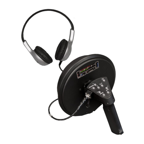
NR-900S Operation Manual 2. NR-900S COMPLETE SET (fig. 2) Table 1 NR-900S main unit with “Pistol-grip” and control unit Carry bag Headphones Car power adapter Soshine SC-S1 battery charger AC power adapter Target imitator (test unit) Soshine 18650 rechargeable cells Operation manual (not shown) Fig. -
Page 7: Main Technical Parameters
NR-900S Operation Manual 3. MAIN TECHNICAL PARAMETERS Target detection range Standard imitator - test unit not less 1 m (maximum probing signal output & maximum receiver sensitivity Probing signal level -max 0 dB -mid -6 dB -min -12 dB Receiver input signal attenuation... -
Page 8: Function
The receiver inputs switching as well as headphones volume control is available from the device control panel. NR-900S has three output levels for radiated probing signal with 6 dB step and four levels of the receiver input signal attenuation each of 10 dB. -
Page 9: Design
(transmitting and receiving) attached to the 250 mm reflector. Main lobes of antennas radiation pattern are oriented along their geometrical axis. NR-900S is made in dust- and waterproof version and has robust enclosure, ensuring safe operation within wide range of temperatures. -
Page 10: Nr-900S Display
NR-900S Operation Manual 5.2 NR-900S DISPLAY (fig. 4) SOUND AT T Fig. 4 – NR-900S display 1. PWR - probing signal level 3 red LEDs indication. Each LED corresponds to 6 dB output level increase. If the LEDs are dead - the transmitter is off.). -
Page 11: Control Unit
NR-900S Operation Manual 5.3 CONTROL UNIT. The battery compartment for two Soshine 18650 rechargeable cells is located inside the handle (see fig. 7). Fig. 5 – Control unit 1 – Control panel 2 – ‘Pistol-drip’ handle 3 – Headphones jack Fig. -
Page 12: Control Panel
NR-900S Operation Manual Fig.7 ‘Pistol-grip’ battery compartment (1) and battery holder with cells (2) 5.4 CONTROL PANEL (fig. 8): PWR + & PWR – buttons (pos.1) are used for probing signal output adjustment: + for increase and – for decreasing its level. -
Page 13: Accessories
NR-900S Operation Manual 6. ACCESSORIES 6.1 IMITATOR Target Imitator (test unit) is intended for NR-900S workability control (fig. 9). Imitator represents high- frequency semi-conductor diode (2D521A referring to the Russian classification) Fig. 9 NR-900S Imitator (test unit) in a 14 x 165 mm solid plastic body. -
Page 14: Charger
Soshine SC-S1 max Charger (fig. 11) is intended for rechargeable cells charging. The battery charging is performed in an automatic mode and does not need any operator’s assistance. Fig. 11 NR-900S standard Charger complete set. 1 – Soshine SC-S1 max charger unit 2 – Soshine DС 12V car adapter 3 –... -
Page 15: Nr-900S Operation
Operating NR-900S keep corresponding safety measures Safety precautions for the open RF emitters: - Do not direct NR-900S antenna to the human eyes from the distance less than one meter. - Avoid prolonged presence of personnel in a main lobe of NR- 900S antenna’... -
Page 16: Getting Started
NR-900S Operation Manual 7.2 GETTING STARTED Take NR-900S components out of standard packing. Insert two fresh rechargeable cells (fig. 12) into the battery compartment (1) keeping the cells polarity specified on the compartment side wall (watch an arrow!). Watch cells polarity! Fig. - Page 17 NR-900S Operation Manual Connect the Control unit to the main unit and fix it (fig.13): - Turn quick-release-base-plate rotary latch (on the back side of the Main unit) clockwise (fig. 11, step1) Main unit Control unit Fig. 13 Control unit coupling...
- Page 18 NR-900S Operation Manual 1. Push On button to switch on the device. The following modes are set on default: – transmitter is on (bottom PWR LED are on) – receivers are on in a search mode ( LED is on) –...
-
Page 19: Nr-900S Workability Test
PWR is on) - Place standard imitator (item 7 at the fig. 2) in a space free from any electronic equipment or gadget. - Point out NR-900S antenna to imitator from the distance of 0,4 m Imitator 0.4 m Fig. 15 NR-900S operation test by means of standard imitator... -
Page 20: Nr-900S Safety Precaution
NR-900S Operation Manual USEFUL HINT: An original schematic design enables to supply NR-900S operator with an outstanding feature: searching for illegal electronics the NLJD user takes notice of an audio alarm signal (tiny beep-beep) prior to custom LED indication. This point is very important when an operator (a sapper) is... -
Page 21: Detector Operation In 'Listen' Mode
NR-900S Operation Manual 7.5 DETECTOR OPERATION IN ‘LISTEN’ MODE This mode is intended for detecting the target’s status (active of switched off) or confirmation the fact that this particular target does not served as a cover for a real active (electronic or mechanical) device. -
Page 22: Detector Operation In 'Search' Mode
NR-900S Operation Manual 7.6 DETECTOR OPERATION IN ‘SEARCH’ MODE - Switch on Detector and carry out its workability test referring pos. 7.3. - Switch over Detector to the ‘SEARCH’ mode (LED is on). - Push ATT(+) button to adjust maximal receiver sensitivity. -
Page 23: Packing
NR-900S Operation Manual 8. PACKING By the end of practical operation do the following: Switch off the Detector. Disconnect Control unit from the Main one. Remove cells from the battery compartment. Unplug headphones from the Main unit. -
Page 24: Emergency Actions
NR-900S Operation Manual 9. EMERGENCY ACTIONS In case of the equipment malfunction that cannot be corrected by the operator, Detector operation should be stopped. If Detector exposed external mechanic, electromagnetic or climatic impact and temporarily lost its workability, then before restoring the operation it is required carry out its visual checks and functional test referring pos. -
Page 25: Battery Charging
NR-900S Operation Manual 10. BATTERY CHARGING (fig. 16). Insert 2 or 4 cells (pos.3) into Soshine Charger chamber (if necessary slide ‘minus’ spring contact) Pay special attention to cells polarity referring indication on the charger chamber Couple AC power adapter or DC 12V car adapter to the socket on a side wall of the Charger (pos. - Page 26 NR-900S Operation Manual Charger LED indication (Fig. 16, pos.1) Table 5 Charging process status LED light mode Charger workability self -test 4 x LED light red then switch over to green Alter green to red Defective or cells of a wrong type...
- Page 27 NR-900S Operation Manual Charger operation precautionary measures - Do not try to charge primary cells! That can initiate an explosion and provoke the fire. Acceptable elements should have an inscription “Rechargeable”. - Do not block vent holes on the bottom of the charger housing.
-
Page 28: Maintenance
ATTENTION! IT IS FORBIDDEN TO DISASSEMBLE THE DEVICE! GENERAL INSTRUCTIONS The NR-900S maintenance should be carried out by the personnel who studied the Operation Manual and have practical experience of NLJD usage. To keep NLJD in fault-free and ready-to-use condition the following maintenance are provided: –... - Page 29 – charge the batteries; – perform the device workability test; – remove the batteries; – pack NR-900S components into the carry bag. Scheduled maintenance – charge the batteries. ROUTINE REPAIR The defective device repair, adjustment and setting-up should be carried out by authorized personal at the Manufacturer’s...
-
Page 30: Shipping And Storage
80 % under +25C NOTE: THE BATTERIES SHOULD BE STORED IN A CHARGED STATE ONLY. 13. CERTIFICATE OF ACCEPTANCE Non-linear Junction Detector NR-900S serial No _____________ is in conformity with the main technical parameters and is accepted for use. Seller _______________... -
Page 31: Warranty
NR-900S Operation Manual 14. WARRANTY NR-900S warranty period is 12 months from the date of sale. Manufacturer guarantees normal functioning of the device on the assumption of the following all requirements of this Manual by the User and in case of malfunction within the Warranty period Manufacturer will repair the device free of charge. - Page 32 NR-900S Operation Manual FOR NOTES _______________________________________________________ _______________________________________________________ _______________________________________________________ _______________________________________________________ _______________________________________________________ _______________________________________________________ _______________________________________________________ _______________________________________________________ _______________________________________________________ _______________________________________________________ _______________________________________________________ _______________________________________________________ _______________________________________________________ _______________________________________________________ _______________________________________________________ _______________________________________________________ _______________________________________________________ _______________________________________________________ _______________________________________________________ _______________________________________________________ _______________________________________________________ _______________________________________________________...
Need help?
Do you have a question about the NR-900S and is the answer not in the manual?
Questions and answers