Advertisement
Table of Contents
- 1 Limited Warranty
- 2 Table of Contents
- 3 Section 1 - Introduction
- 4 Section 2 - Specifications
- 5 Section 3 - Physical Dimensions & Weights
- 6 Section 4 - Installation
- 7 Section 5 - Wiring
- 8 Section 6 - Accuvalve Insight Configuration Software
- 9 Section 7 - Optional Bacnet Ms/Tp
- 10 Section 8 - Maintenance
- 11 Appendix A - Actuator Drawings
- 12 Appendix B: Bluetooth
- 13 Appendix C: Accunet
- Download this manual
Installation & Operation Manual
Manufactured by:
21 Commerce Drive
Danbury, CT 06810 USA
WWW.ACCUTROLLLC.COM
Contents of this Manual are Subject to Change Without Notification
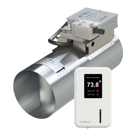
- Model AVT6000
Airflow Control Valve
Patented: U.S. 6,991,177 & 7,543,759
Accutrol Representative:
AVT6000 MANUAL REV B, 2020-05-29, ECN 2627
Advertisement
Table of Contents

Related Manuals for Accutrol AccuValve AVT6000


Summary of Contents for Accutrol AccuValve AVT6000
- Page 1 Installation & Operation Manual - Model AVT6000 Airflow Control Valve Patented: U.S. 6,991,177 & 7,543,759 Manufactured by: Accutrol Representative: 21 Commerce Drive Danbury, CT 06810 USA WWW.ACCUTROLLLC.COM AVT6000 MANUAL REV B, 2020-05-29, ECN 2627 Contents of this Manual are Subject to Change Without Notification...
-
Page 2: Limited Warranty
Installation & Operation Manual - Model AVT6000 LIMITED WARRANTY Accutrol LLC, having its principal place of business at 21 Commerce Drive, Danbury, CT USA ® ("Manufacturer") warrants its AccuValve , Model AVT6000 product (the "Products") as follows: 1. Limited Warranty. -
Page 3: Table Of Contents
Installation & Operation Manual - Model AVT6000 TABLE OF CONTENTS LIMITED WARRANTY ........................ ii TABLE OF CONTENTS ....................... iii SECTION 1 - INTRODUCTION ....................4 SECTION 2 - SPECIFICATIONS ....................6 SECTION 3 – PHYSICAL DIMENSIONS & WEIGHTS ............11 SECTION 4 - INSTALLATION .................... -
Page 4: Section 1 - Introduction
Installation & Operation Manual - Model AVT6000 SECTION 1 - INTRODUCTION The AVT6000 product family is intended for applications that require accurate and repeatable airflow measurement with high turn-down that achieves precise control using an external PI controller. The AVT6000 incorporates a state-of-the-art vortex shedding digital transmitter with an intuitive user-interface software known as the AccuValve Insight. - Page 5 Installation & Operation Manual - Model AVT6000 1.2 Model Code A V T 6 VALVE MATERIAL 2 = 304ss, 20 Ga 3 = 316ss, 20 Ga 4 = Aluminum, 16 Ga 5 = PFA Coated 304ss, 20 Ga 6 = High Temp. 304ss, 20 Ga VALVE SIZE 06 = 6"...
-
Page 6: Section 2 - Specifications
1/8 Unit Load Receiver Input Impedance Network bias and EOL Termination not provided within the Transmitter AccuNet (Optional) 2-wire Controller Area Network Bus for summing 2 to 20 Accutrol Device Airflows 120-ohm EOL network termination resistors are required Reference Appendix C for details... - Page 7 Installation & Operation Manual - Model AVT6000 MATERIALS OF CONSTRUCTION Model Code Material Designator (2) 304SS (3) 316SS (4) Aluminum (5) PFA Coated (6) High Temp Housing 304LSS 316LSS Alum. 5052-H32 PFA Coated 304SS 304LSS Compression Section 304LSS 316LSS Alum. 5052-H32 PFA Coated 304SS 304SS Static Regain Section...
- Page 8 Installation & Operation Manual - Model AVT6000 2.1 Operating Range The operating range of each AccuValve is provided below along with a characteristic curve showing the relationship between the minimum operating pressure and maximum airflow volume as tested in accordance with ANSI/ASHRAE STD 130. 0.45 0.40 0.35...
- Page 9 Installation & Operation Manual - Model AVT6000 0.45 0.40 0.35 0.30 12” AccuValve Operating Range: 0-1790 CFM 0.25 Min. Measurement: 180 CFM 0.20 0.15 0.10 0.05 0.00 1000 1200 1400 1600 1800 Max Airflow (CFM) 0.45 0.40 0.35 0.30 14” AccuValve 0.25 Operating Range: 0-2750 CFM Min.
- Page 10 Installation & Operation Manual - Model AVT6000 0.45 0.40 0.35 0.30 12x24” AccuValve 0.25 Operating Range: 0-4000 CFM Min. Measurement: 350 CFM 0.20 0.15 0.10 0.05 0.00 1000 1500 2000 2500 3000 3500 4000 Max Airflow (CFM) 0.45 0.40 0.35 0.30 12x36”...
-
Page 11: Section 3 - Physical Dimensions & Weights
Installation & Operation Manual - Model AVT6000 SECTION 3 – PHYSICAL DIMENSIONS & WEIGHTS 3.1 Round Valve Sizes 12” (305mm) “H” “D” “L” Dimensions Weight Valve Model “D” “L” “H” Stainless Steel Aluminum Size Lbs. Lbs. 5.88 7.88 9.88 11.88 11.8 13.88 13.6... -
Page 12: Section 4 - Installation
AccuValve is not position sensitive, it can be installed in any plane or rotational axis without having impact on the performance. NOTE: Screws, nuts, fasteners, duct sealant, hangers, companion flanges and gaskets are NOT provided by Accutrol. Page 12 Contents of this Manual are Subject to Change Without Notification... - Page 13 5. For clean air applications, apply UL181 compliant foil tape over the valve/duct seams. For corrosive exhaust applications, apply PTFE tape (available from Accutrol) over the valve/duct seams. 6. Secure both ends of valve to the duct using draw band clamps.
- Page 14 Installation & Operation Manual - Model AVT6000 4.2 Rectangular Valve Installation Diagrams Valve Sizes 18 and 24 1. Verify the opening in the duct is properly sized for the valve and installation method being used. Also verify both ends of the duct where the valve is to be attached are true and square before attempting to install valve. If the duct ends are not square and true, do not attempt to install valve as it will not operate properly.
-
Page 15: Section 5 - Wiring
Installation & Operation Manual - Model AVT6000 SECTION 5 – WIRING 5.1 AVT6000 Transmitter Description Cover Tab Slot Captive Thumb Screw for Removing/Securing Cover Connection from optional monitor using factory supplied cable. NOTE: If a direct conduit connection is required, remove strain relief fitting and Alternate Cable Entry replace with a .875 (22mm) conduit... -
Page 16: Section 6 - Accuvalve Insight Configuration Software
“Register Product Key”. f. You will now be able to use the AccuValve Insight Software on this computer. If you have any problems, contact Accutrol LLC at 203-445-9991. Page 16 Contents of this Manual are Subject to Change Without Notification... - Page 17 Installation & Operation Manual - Model AVT6000 6.4 Connecting the PC to the AVT Transmitter 6.4.1 Connecting to a standard AVT6000 using a USB cable. Note: If 24VAC is applied and the USB is connected beforehand, or if the switch position is changed while a USB connection is active, the transmitter will revert to bootloader mode and will not function properly.
- Page 18 Installation & Operation Manual - Model AVT6000 6.4.2 Connecting to AVT6000-W (with optional wireless Bluetooth module) Windows 10 Device with AVT6000-W Bluetooth Ver 4.2 and AccuValve Insight Software Bluetooth Antenna Note: Reference Appendix B for Bluetooth Connection Details. 6.4.3 Connecting to a remote monitor such as the AFM1 Airflow Monitor Windows 10 Device with AccuValve Insight Software AFM1 Airflow Monitor...
- Page 19 This can be fixed by now downloading the driver package which Accutrol has provided. If the correct driver is missing, insight will likely display “No Accutrol Device Located” after clicking Locate Accutrol USB Devices despite the PC being connected to the transmitter board.
- Page 20 Installation & Operation Manual - Model AVT6000 4. Find the .exe files called “CP210xVCPInstaller” and run the x64 version or x86 version depending on the type of operating system that’s on your pc. 5. After installation, Insight should successfully locate a COM port when connected to an AccuValve transmitter.
- Page 21 Installation & Operation Manual - Model AVT6000 The Airflow Volume Gauge provides the real-time measurement of the volumetric air flowing through the AccuValve. The range of this gauge is determined by the size of the valve and it cannot be reset in the field. 6.5.3 Valve Airflow Gauge The Valve Airflow Volume Gauge provides the real-time measurement of the volumetric air flowing through the AccuValve.
- Page 22 Installation & Operation Manual - Model AVT6000 6.5.5 Analog Output Configuration The AVT’s Analog Output is primarily used to provide an analog signal representing the Airflow Volume flowing through the valve. The signal type and full-scale range of the Analog Output are user-defined values that are configured by clicking on the boxes adjacent to each heading.
- Page 23 Installation & Operation Manual - Model AVT6000 6.5.6 Sensor Frequency Signals The AccuValve measures airflow using vortex shedders that are incorporated in the compression zone of each chamber inside the valve. Each vortex shedder provides an independent frequency-based signal that is directly proportional to the air flowing through the chamber.
- Page 24 Installation & Operation Manual - Model AVT6000 ➢ To Transmitter Flash Memory: This will save the contents of the transmitter RAM memory to the transmitter nonvolatile FLASH memory. ➢ To File: This will open a window that will enable you to save the AVT configuration parameters to the computer hard drive or other nonvolatile storage device connected to the computer.
- Page 25 Installation & Operation Manual - Model AVT6000 the Airflow Balancer to correlate the AVT6000 airflow measurement to a field airflow measurement. The graph below shows the effect the Equal % Cal Adj. has over the entire operating range. 1000 -10% Adj.= -100 CFM change Factory Cal.
- Page 26 Installation & Operation Manual - Model AVT6000 The primary application for AccuNet is in laboratories that have multiple VAV fume hoods which require the total lab exhaust airflow to be instantly tracked by the supply airflow to maintain the proper room pressurization. AccuValves must be equipped with the optional AccuNet Module to operate on the AccuNet Network.
-
Page 27: Section 7 - Optional Bacnet Ms/Tp
SECTION 7 – OPTIONAL BACNET MS/TP BACnet® is a standard data communication protocol designed specifically for building automation and control networks. The Accutrol AVT6000 Transmitter uses the BACnet MS/TP (Master-Slave/Token Passing) protocol which is a type of MAC layer implemented using the EIA- 485 signaling standard. - Page 28 Objects; AI and AV shall support the COV_INCREMENT property which shall also be writable. 7.1.1 Save Active Configuration to Nonvolatile Flash Memory The Accutrol AVT6000 Transmitter has both volatile (RAM) and nonvolatile (Flash) memory. RAM memory does not have a limitation on the number of times it can be written, whereas Flash memory does.
-
Page 29: Section 8 - Maintenance
Installation & Operation Manual - Model AVT6000 SECTION 8 – MAINTENANCE Scheduled maintenance for the AVT6000 is not required; however each AccuValve does include an access cover which can be removed to inspect the airflow sensors if desired. 8.1 Round Valve Access Cover CAUTION: Wear eye protection, cut-resistant gloves and clothing suitable for working with sheet metal. - Page 30 Installation & Operation Manual - Model AVT6000 8.2 Rectangular Valve Access Cover CAUTION: Wear eye protection, cut-resistant gloves and clothing suitable for working with sheet metal. Failure to do so may result in personal injury. Access Cover 8.2.1 The access cover is secured to the valve using (4) #2 blunt-head Phillips head screws. To inspect the sensors, remove the access cover by removing the screws using a #2 Phillips head screw driver.
-
Page 31: Appendix A - Actuator Drawings
Installation & Operation Manual - Model AVT6000 APPENDIX A – ACTUATOR DRAWINGS Appendix Model Code Actuator Actuator Description Page Actuator Identifier Part Number AVT6xxx-02- Fail Last Position, 0-10v, High Speed 20-0008 AVT6xxx-03- Fail Last Position, 2-10v, High Speed 20-0009 AVT6xxx-04- Fail Open or Closed, 0-10v, High Speed 20-0010 AVT6xxx-05-... - Page 32 Installation & Operation Manual - Model AVT6000 Page A2...
- Page 33 Installation & Operation Manual - Model AVT6000 Page A3...
- Page 34 Installation & Operation Manual - Model AVT6000 Page A4...
- Page 35 Installation & Operation Manual - Model AVT6000 Page A5...
- Page 36 -22°F to 122°F (-30°C to 50°C) ® Each actuator is installed, configured and tested on the AccuValve prior to shipping from the Accutrol factory. Storage Temperature: -40°F to 176°F (-40°C to 80°C) The following instructions are provided as a reference for replacing an actuator in the field.
-
Page 37: Appendix B: Bluetooth
To Connect to the AccuValve® with Bluetooth Launch the AccuValve® Insight application and select “Locate BT Devices”. Only Bluetooth enabled Accutrol devices within range will be discovered and listed by their TAG names. Double-click on the appropriate device to connect. -
Page 38: Appendix C: Accunet
Installation & Operation Manual - Model AVT6000 APPENDIX C: ACCUNET This guide provides a general description of AccuNet™, it’s intended applications and instructions for performing the field network configuration. Description AccuNet™ is a high-speed serial bus that is designed to provide a room-level network for summing the airflow volume of multiple AccuValves while providing a single analog signal representing the total sum of the AccuValve airflows. - Page 39 Installation & Operation Manual - Model AVT6000 How to Field-Configure the AccuNet Network Devices Each AccuValve on the network must be field-configured using the AccuValve Insight Program for the purpose of; assigning a unique network address to each device, associating each device on the network with one another, and configuring one device as the network Totalizer.
- Page 40 Installation & Operation Manual - Model AVT6000 Step 3: Configure each AccuValve in the Network (this example is a 4 AccuValve network) 3-1. Configure the first AccuValve in the network. 3-1a. Connect to the first AccuValve on the network and open AccuValve Insight. 3-1b.
- Page 41 Installation & Operation Manual - Model AVT6000 The utility will now assign a unique network address to this AccuNet Module and AccuValve TAG name will be assigned as the TAG name of this AccuNet Module. 3-3d. Close Insight and disconnect from the AccuValve. 3-4.
- Page 42 Installation & Operation Manual - Model AVT6000 Each item that was configured in Step 3 should appear in the list. If any devices are missing, there may be problem with the physical network or one of the devices was not configured properly. If only the Totalizer appears on the list, check the network wiring and verify the 120-ohm termination resistors are installed on each end of the network.
- Page 43 Installation & Operation Manual - Model AVT6000 Figure 1: Lab with (4) AccuValves on the AccuNet Network Total Exhaust Flow Supply Flow FHEV1 GEV1 FHEV2 FHEV3 TOTALIZER Lab Controller Supply Ctrl. Signal Total Exhaust Air Flow Supply Air Flow SAV1 AVC6 AVC6 AVC6...
Need help?
Do you have a question about the AccuValve AVT6000 and is the answer not in the manual?
Questions and answers