Advertisement
Table of Contents
- 1 Table of Contents
- 2 Section 1 - Introduction
- 3 Section 2 - Specifications
- 4 Section 3 - Model Code Description
- 5 Section 4 - Physical Dimensions & Weights
- 6 Section 5 - Installation
- 7 Section 6 - Wiring
- 8 Section 7 - Output Configuration
- 9 Section 8 - Tek-Air Controller Direct Input
- 10 Section 9 - Maintenance
- 11 Appendix A: Actuator Technical Data Sheets
- 12 Appendix B: Document Revision History
- Download this manual
Installation & Operation Manual - Model AV3000
Manufactured by:
21 Commerce Dr,
Danbury, CT 06810
www.accutrolllc.com
Contents of this Manual are Subject to Change Without Notification
Airflow Control Valve
Patented: U.S. 6,991,177 & 7,543,759
Accutrol Representative:
AV3000 MANUAL-ACCUTROL-JANUARY 2019, ECN 2433
Advertisement
Table of Contents

Related Manuals for Accutrol AccuValve AV3000


Summary of Contents for Accutrol AccuValve AV3000
- Page 1 Installation & Operation Manual - Model AV3000 Airflow Control Valve Patented: U.S. 6,991,177 & 7,543,759 Manufactured by: Accutrol Representative: 21 Commerce Dr, Danbury, CT 06810 www.accutrolllc.com AV3000 MANUAL-ACCUTROL-JANUARY 2019, ECN 2433 Contents of this Manual are Subject to Change Without Notification...
- Page 2 Installation & Operation Manual - Model AV3000 LIMITED WARRANTY Accutrol LLC, having its principal place of business at 21 Commerce Dr, Danbury, CT ® ("Manufacturer") warrants its AccuValve , Model AV3000/H-AV3000 product (the "Products") as follows: 1. Limited Warranty. Manufacturer warrants that the Products sold hereunder will be free from defects in material and workmanship for a period of sixty (60) months from the date of purchase.
-
Page 3: Table Of Contents
Installation & Operation Manual - Model AV3000 TABLE OF CONTENTS LIMITED WARRANTY ......................ii TABLE OF CONTENTS ....................iii SECTION 1 - INTRODUCTION ..................1 SECTION 2 - SPECIFICATIONS ..................3 SECTION 3 – MODEL CODE DESCRIPTION ..............4 SECTION 4 – PHYSICAL DIMENSIONS & WEIGHTS ........... 5 SECTION 5 - INSTALLATION .................. -
Page 4: Section 1 - Introduction
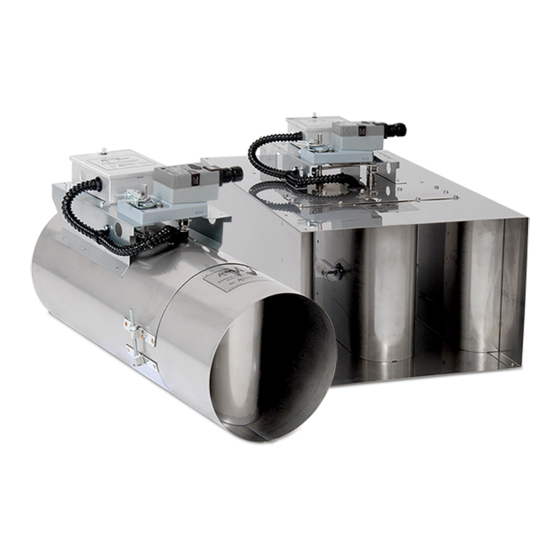
Installation & Operation Manual - Model AV3000 SECTION 1 - INTRODUCTION 1.1 Description ® The AV3000 airflow control valve - AccuValve - incorporates high accuracy airflow ® sensing with a revolutionary but simple design. The AccuValve divides the airflow into two equal chambers using an airfoil shaped compression section. Each chamber is comprised of a vortex shedding airflow sensor, a modulating control blade and a static regain section. - Page 5 Installation & Operation Manual - Model AV3000 1.3 AV3200 Major Components Identified 1.3.1 AV3200-18 and -24 Linkage Drive Shaft Airflow Center Electric Actuator Airflow Transmitter Compression Sensor Section Access Cover Side Compression Section Airflow Inlet View Follower Shaft Center Regain Section Housing Side...
-
Page 6: Section 2 - Specifications
Installation & Operation Manual - Model AV3000 SECTION 2 - SPECIFICATIONS AIRFLOW ACCURACY: +/- 5% of Reading SPEED OF RESPONSE: <1 second SHUT OFF LEAKAGE: Model AV3100: < 1.5% Transmitter Factory FS @ Max Operating Pressure Model AV3100-S: < 0.5% Transmitter Factory FS Model AV3200: <... -
Page 7: Section 3 - Model Code Description
Installation & Operation Manual - Model AV3000 SECTION 3 – MODEL CODE DESCRIPTION SHAPE 1 = Round 2 = Rectangular VALVE MATERIAL 1 = Galv. Steel, 20 Ga. (rectangular valves only) 2 = 304SS, 20 Ga. 3 = 316SS, 20 Ga. 4 = Aluminum, 16 Ga. -
Page 8: Section 4 - Physical Dimensions & Weights
Installation & Operation Manual - Model AV3000 SECTION 4 – PHYSICAL DIMENSIONS & WEIGHTS 4.1 Round Sizes 12” (305mm) “H” “D” “L” Weight Valve Model lbs. AV3100-06 5.88 AV3100-08 7.88 AV3100-10 9.88 AV3100-12 11.88 11.8 AV3100-14 13.88 13.6 4.2 Rectangular Sizes “H”... -
Page 9: Section 5 - Installation
7. Reference the appropriate diagram provided in this section for installation details. NOTE: Screws, nuts, fasteners, duct sealant, hangers, companion flanges and gaskets are NOT provided by Accutrol. Secure Using Sheet Duct Support Metal Screws 14”... - Page 10 Installation & Operation Manual - Model AV3000 Draw Band 14” (356mm) Minimum Clearance For Access Round Valve Installation – Standard Slip-Fit Valve - Using Draw Band 3/8” bolts, lock-washers and nuts Duct Support Gasket 14” (356mm) Minimum Clearance For Access Round Valve Installation –...
- Page 11 Installation & Operation Manual - Model AV3000 Apply Duct Sealant Secure Using Sheet metal Screws 14" (356mm) Minimum Clearance Rectangular Valve Installation – Standard Slip Fit – Using Sheet Metal Screws 3/8" Bolts, Lock Washers and Nuts 14" (356mm) Minimum Clearance Rectangular Valve Installation –...
-
Page 12: Section 6 - Wiring
Installation & Operation Manual - Model AV3000 SECTION 6 – WIRING 6.1 Transmitter Wiring Thumb Screw 6.1.1 Loosen the thumb-screw and remove cover. Reference the label on the inside of cover for a description of transmitter connections. 6.1.2 Remove the Power and Signal Plugs from board and route cables through the strain relief fitting. - Page 13 Installation & Operation Manual - Model AV3000 6.3 Field Wiring Schematics The following diagrams are intended to be used as examples for connecting the ® AccuValve AV3000 to Field Devices. Reference the inside of transmitter cover for identification of connectors. NOTE: Use 16-22 AWG Shielded Cable. ®...
- Page 14 Installation & Operation Manual - Model AV3000 ® 6.3.3 Typical wiring between AccuValve and Tek-Air SmartLab Controller ® equipped with the AccuValve Direct Input board. Cable Shown Below: Tek-Air SLC Controller 20 AWG 3-Conductor AccuValve, Model AV3000 Shielded Plenum (Windy City Wire #003330) Transmitter WHITE Signal (2-10)
-
Page 15: Section 7 - Output Configuration
Installation & Operation Manual - Model AV3000 SECTION 7 – OUTPUT CONFIGURATION ® Each AccuValve is tested and calibrated in the factory and performance is verified to ensure accuracy. The transmitter Full Scale Range is set per the table in Section 2 and the Analog Output Signal has been configured to provide either Voltage (0-10v or 2-10v) or Current (0-20mA or 4-20mA) by using Jumpers JP1 and JP4. -
Page 16: Section 8 - Tek-Air Controller Direct Input
Installation & Operation Manual - Model AV3000 SECTION 8 – TEK-AIR CONTROLLER DIRECT INPUT 8.1 Overview The Tek-Air SmartLab (SLC2000) and Fume Hood (FVC2000) Controllers can be ordered from the factory with an “AccuValve Direct” input board installed. This board ®... - Page 17 Installation & Operation Manual - Model AV3000 8.3 AV3000 Transmitter Configuration In order for the AV3000 Transmitter to operate properly with the “AccuValve ® Direct Input Board” the transmitter output jumpers must be configured for 2-10 v operation and the Transmitter Full-Scale Range must remain set to the factory default values as shown below.
- Page 18 Installation & Operation Manual - Model AV3000 8.4 Fume Hood Controller Configuration Standard calibration constants for the FVC “VorTek Direct” input have been derived for each AV3000 transmitter range. Using the FVC2000 Configuration Tool, set the three VorTek parameters as show below for the given size valve. AV3100-06 AV3100-08 AV3100-10...
-
Page 19: Section 9 - Maintenance
Installation & Operation Manual - Model AV3000 SECTION 9 – MAINTENANCE 9.1 Maintenance ® Scheduled maintenance for the AV3000 is not required, however, each AccuValve does include an access cover which can be removed to inspect the airflow sensors if desired. - Page 20 Installation & Operation Manual - Model AV3000 9.1.1 Rectangular Valve Access Cover Equipment Required: 5/16” socket with ratchet drive or power driver, safety glasses and safety gloves suitable for sheet metal working. Access Cover 1. The access cover is secured to the valve using (12) Tek-Screws. Remove the (12) Tek-Screws using a 5/16”...
-
Page 21: Appendix A: Actuator Technical Data Sheets
Installation & Operation Manual - Model AV3000 APPENDIX A: ACTUATOR TECHNICAL DATA SHEETS Contents of this Manual are Subject to Change Without Notification... -
Page 22: Appendix B: Document Revision History
Installation & Operation Manual - Model AV3000 APPENDIX B: DOCUMENT REVISION HISTORY New Revision: JULY 2017 New Filename: AV3000 MANUAL-ACCUTROL-JULY 2017.DOC Section Description of Change Cover Revised address New Revision: Dec 2012 New Filename: AV3000 MANUAL-ACCUTROL-DEC 2012.DOC Section Description of Change Cover Revised filename.
Need help?
Do you have a question about the AccuValve AV3000 and is the answer not in the manual?
Questions and answers