Table of Contents
Advertisement
Quick Links
RS-232C to Wireless LAN
(IEEE802.11n/a/b/g)
FXR2000-G Setup Guide
CONTEC CO.,LTD.
The FXR2000-G is a wireless LAN COM converter that conforms to IEEE 802.11n/a/b/g standards.
Packing List
- Main unit (FXR2000-G)...1
- Setup Guide...1
- Power terminal connector...1
- Retention bracket...1
- Bracket screw M3 x 6...1
- Bracket screw M3 x 5...3
How to Obtain Service
For replacement or repair, return the device freight prepaid, with a copy of the original invoice. Please obtain a Return
Merchandise Authorization number (RMA) from the CONTEC group office where you purchased before returning any
product. *No product will be accepted by CONTEC group without the RMA number. This device sold for OEM vendor
only.
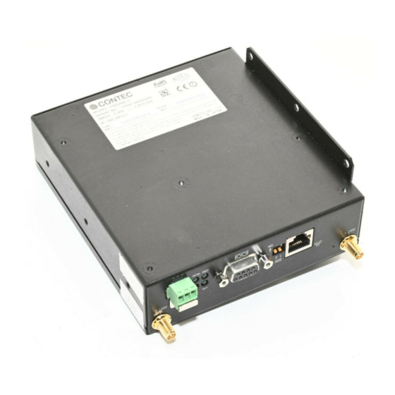
Part Names and Functions
Power supply connector :
Used to supply power to the product. Also used to ground the product.
LED :
Indicates the status of the power supply, wired LAN and wireless LAN.
Refer to LED display for details.
Serial port connector :
A standard serial port with a DB-9 (female) connector. To connect to a
computer, use a standard (straight-through) serial cable
(male-to-female).
For details, see the Serial Port Pin Assignments and Serial port Setting.
DIP switch :
Used for Default setup
See DIP Switches for the setting method.
LAN port :
Connects to a hub or PC through 10-BASE-T/100-BASE-TX.
Antenna connectors : Connect to the antennas.
LED display
LED name
Status
ON
Indicates that the device is operating.
( POWER)
Flashing Indicates that the device is being started (This device turned on)
When the product is configured as a station, the LED being ON indicates that the
ON
product is logged in an access point.
Indicates data is being transmitted to or received from the device connected through
WLAN
Flashing
wireless LAN.
When the product is configured as a station, the LED being OFF indicates that the
OFF
product is not logged in an access point.
ON
Indicates that a wired LAN has been connected.
Indicates that the product is transmitting/receiving data to/from the connected
Flashing
LAN
terminal through wired LAN.
Indicates that the product is not transmitting/receiving data to/from the connected
OFF
terminal through wired LAN.
COM
Flashing Sending or receiving COM data
DIP switches
ON
OFF
Turning on this switch flashes the POWER, WLAN, COM LEDs.
If the switch is turned off before the LEDs change their status from flashing to
1
INIT
-
ON (about 3 seconds), all the settings are restored to the default settings after
the product is started next time. Reboot the product after the LEDs stop
flashing. *1
This switch is not used
2
-
-
*1 Always reboot the product after the flashing stops. The flashing continues for a little while after the product is switched off
during initialization by switching on and off the INIT switch. This indicates internal memory files are being deleted. The
internal memory files may be damaged and the product may not start up properly if the power is switched off before the
flashing stops.
Pin Layout
Power Connectors
Name
Power
Power terminal connector (included in the package): MC1,5/3-ST-3,5 (made by Phoenix Contact Inc.)
connector
The applicable cable is AWG28-16. (The cable length must meet the power supply specifications.)
Secure the connector with a retention bracket. Connect the power cable to the power terminal
connector by screw connection.
Pin number
Signal
3
Vi+
2
Vi-
1
FG
Serial Port Pin Assignments
Abbreviated
Pin No.
Signal name
name
1
DCD
Carrier detect
2
RxD
Received data
3
TxD
Transmitted data
4
DTR
Data terminal ready
5
GND
Signal ground
6
DSR
Modem ready
7
RTS
Request to send
8
CTS
Clear to send
9
Not Used
-
1
- Warranty Certificate...1
- Mounting bracket...3
- Bracket screw M3 x 8...4
LED display
Operation / function
Function
Description
3
Power (5-30VDC±5%)
2
Power (GND)
1
Frame Grand
Input-
Output
Output
Output
1
6
Input
Input
−
5
9
Output
Input
Output
-
UTP Port Pin Assignments
Pin No.
Signal name
8
Not used
7
Not used
6
RD-
5
Not used
4
Not used
3
RD+
2
TD-
1
TD+
Attaching the Antenna Connectors
The following describes how to attach the supplied antenna
connectors.
Attaching a retention bracket
Plug in the power terminal connector to the power
connector and attach the retention bracket using a bracket
screw. The tightening torque of the bracket screw is
0.588 Nm.
Setup Methods
Using the Web browser.
Preparation before Setup
Since the product is set up via network, use a computer that can be connected to the network.
Connect the computer to the network and use a Web browser for setting.
Connecting the product for the first time
(1)
Use a regular Ethernet cable and connect this product to the PC. .
(2)
Select an IP address 192.168.0.X (e.g. 192.168.0.100) for the PC, which is not the same address as for this product.
And then set the subnet mask to 255.255.255.0.
Windows:
Click [Start] - [Control Panel] - [Network Connection], and then right-click the icon for local area connection to
open up the [Properties] screen. Select [Internet Protocol (TCP/IP)] from the [General] tab and click [Properties].
Set up the IP address and subnet mask, and if necessary, default gateway and DNS server on the opened [Internet
protocol (TCP/IP) properties] window.
Change the settings
(1)
Use a regular Ethernet cable and connect this product to the PC.
Setting the Browser
You may have to change the browser settings as well as the IP address and subnet mask for the PC to be connected to this
product via the network.
Changing browser settings
(1)
Networks at companies and schools may use broswers with proxy settings. Proxy is not required as a PC is used to
set up the product, which is on a local network. Disable the proxy settings temporarily when setting up this product
on a Web browser.
For information about how to disable proxy settings, refer to the help section of the Web browser used.
(2)
Enable JavaScript.
For information about how to enable JavaScript, refer to the help section of the Web browser used.
CAUTION
If the Web browser settings have been changed, restore the browser settings to the original settings after the setup of this product has
been completed.
8
1
Cable Installation
Use a regular RS232 cable to connect with FXR2000-G
COM port.
Use a regular Ethernet cable to connect with FXR2000-G
LAN port.
FXR2000-G
Advertisement
Table of Contents

Related Manuals for Contec FXR2000-G


Summary of Contents for Contec FXR2000-G
- Page 1 For replacement or repair, return the device freight prepaid, with a copy of the original invoice. Please obtain a Return Merchandise Authorization number (RMA) from the CONTEC group office where you purchased before returning any product. *No product will be accepted by CONTEC group without the RMA number. This device sold for OEM vendor only.
- Page 2 Number of channels Serial port Setting Connector 9 pin D-SUB, F (Female) type Use these parameters to configure the serial port on the FXR2000-G to match the settings on the connected serial device. Antenna connector R-SMA Connector x2 External Dimensions (mm) 38(W) x 135(D) x 124(H) Data bits: Number of data bits.
- Page 3 This equipment should be installed and operated with minimum distance 20cm between the radiator & your No part of this document may be copied or reproduced in any form by any means without prior written consent of CONTEC CO., LTD.
- Page 4 FXR2000-G Setup Guide FXR2000-G...
Need help?
Do you have a question about the FXR2000-G and is the answer not in the manual?
Questions and answers