Table of Contents
Advertisement
Quick Links
rev 1.27 / 2021 07 14
PDD-300 pulsed diode driver
User manual
Warning! This equipment may be dangerous.
Please read user manual before starting operations.
Important note. Please measure output with adequate load only (diodes). Resistive load
connected to the output won't destroy the driver, but will severe distort its behavior.
1
Advertisement
Table of Contents

Summary of Contents for OEM PDD-300
- Page 1 1.27 / 2021 07 14 PDD-300 pulsed diode driver User manual Warning! This equipment may be dangerous. Please read user manual before starting operations. Important note. Please measure output with adequate load only (diodes). Resistive load connected to the output won’t destroy the driver, but will severe distort its behavior.
-
Page 2: Table Of Contents
Table of content WARNINGS ..........................3 EXPLANATION OF SYMBOLS ....................3 OVERVIEW / APPLICATIONS ..................... 4 COOLING ..........................4 APPEARANCE / LAYOUT......................4 CONNECTORS / PINS / INTERFACE SIGNALS ................5 INSTALLATION ........................7 OPERATIONS NOTES ....................... 7 TROUBLESHOOTING ....................... 7 INPUT FUSES .......................... -
Page 3: Warnings
Warnings Warning! The equipment is CLASS I ME EQUIPMENT. To avoid risk of electrical shock, the equipment must be protectively grounded. Warning! There is no user-serviceable parts inside the device. Do not self-repair the driver. Do not even open the enclosure, because of electrical shock risk with residual high voltage. -
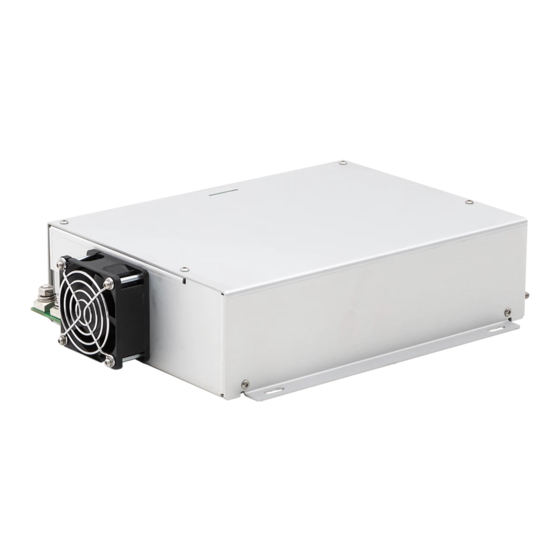
Page 4: Overview / Applications
Overview / Applications PDD-300 is a series of high-power pulsed diode drivers. Peak output power is up to 5kW (with user selectable I and V ), averaged output power is up to 300W. Driver was specially designed for direct diode hair removal application. -
Page 5: Connectors / Pins / Interface Signals
Maximum allowed current in Fault loop is 50mA. +5V TTL pulse should be applied to pin 3 and to pin 8 simultaneously in order to obtain pulsed current from PDD-300. 3 (transparent) PULSE 1 In cases if 0V is applied to one of these... - Page 6 +15V DC Auxiliary +15V DC output. 14 (red) AUXILIARY Maximum output current 50mA. OUTPUT INTERFACE Return of other Interface signals (namely 15 (white/blue) RETURN Fault, Current program and +15V DC) AC POWER INPUT: Molex Minifit MF-6F type PIN (color) DESCRIPTION 1, 4 Pins 1 and 4 are interconnected inside the module 2, 5...
-
Page 7: Installation
• Use four M4 mounting slits on the bottom side of PDD-300 to fix the module in your system. Refer to the Dimensional drawing section for their location •... -
Page 8: Pulse Width Limitations
Approximate formulae to estimate the maximum pulse width in a certain regime is =I*V*T , where T is a maximum pulse width PDD-300 is able to provide with current I and voltage V at its output. E is a maximum extractable energy, which varies from ~200J in standard modifications to ~300J in long pulse modifications. -
Page 9: Specifications
) In given regime, i.e. with given operating current (I), voltage (V) and pulse width (t), pulse energy (E) can be calculated as E=I*V*t. Since internal buffer capacitance of PDD-300 is limited, pulse energy is also limited (E < ). Please contact the factory for further details. - Page 10 OUTPUT POWER DERATINGS Ambient temperature – 40 °C...
-
Page 11: Dimensional Drawing (Standard Version)
Dimensional drawing (standard version) -
Page 12: Dimensional Drawing (Long Pulse Version)
Dimensional drawing (long pulse version) -
Page 13: How To Order
- Output leads – 2pc Environmental protection PDD-300 should not be disposed of with household waste. Please dispose PDD-300 in accordance with the legislation on the management of electronic waste in your country. Name and address of the manufacturer OEM Tech O.O.O. -
Page 14: Electromagnetic Environment - Guidance
Electromagnetic environment – Guidance Standard: IEC 60601-1-2:2014 Environment of intended uses: Professional Healthcare Facility Environment Emission test Limit Electromagnetic environment - Guidance Device uses RF energy only for its internal function. Conducted emission CISPR 11, Group 1, Class A Therefore, its RF emissions are very low and are not likely to cause any interference in nearby electronic Radiated emission CISPR 11, Group 1, Class A... - Page 15 Recommended separation distance: d = 1.2√P for 150 kHz to 80MHz where P is the maximum output power rating of the transmitter in watts (W) according to the transmitter manufacturer and d is the recommended separation distance in meters (m). Power frequency magnetic fields should be at levels Rated power frequency 30 A/m, 50 Hz...
Need help?
Do you have a question about the PDD-300 and is the answer not in the manual?
Questions and answers