Table of Contents
Advertisement
Quick Links
Advertisement
Table of Contents

Related Manuals for Optical dimensions LASER CHECK 6212A


Summary of Contents for Optical dimensions LASER CHECK 6212A
- Page 1 OPTICAL DIMENSIONS™ 2973 Harbor Blvd, #665, Costa Mesa, CA 92626 Phone: (831) 287-0495 i n f o @ o p t i c a - l d i m e n s i o n s . c o m w w w .
-
Page 2: Operations And Specification Manual For The
Dimensions. The information in this document is provided as an aid in the Assembly, Diagnostics, and Operation of the Lasercheck Gage, Components, and Accessories and is not to be used otherwise or reproduced without written consent of Optical Dimensions. The Lasercheck gage is patented technology protected under US Patent Number 5,608,527. -
Page 3: Table Of Contents
Electrical ....................................2 Laser ......................................2 WARRANTY OVERVIEW ............................... 3 LIMITATION OF WARRANTY ..............................3 Contact Optical Dimensions customer service for shipping instructions: ................3 MAINTENANCE ..................................4 Cleaning the Windows ................................4 Assistance ....................................4 INTRODUCTION TO LASERCHECK ............................5 Overview.................................... - Page 4 OPTICAL DIMENSIONS™ 2973 Harbor Blvd, #665, Costa Mesa, CA 92626 Phone: (831) 287-0495 i n f o @ o p t i c a - l d i m e n s i o n s . c o m w w w .
- Page 5 OPTICAL DIMENSIONS™ 2973 Harbor Blvd, #665, Costa Mesa, CA 92626 Phone: (831) 287-0495 i n f o @ o p t i c a - l d i m e n s i o n s . c o m w w w .
- Page 6 OPTICAL DIMENSIONS™ 2973 Harbor Blvd, #665, Costa Mesa, CA 92626 Phone: (831) 287-0495 i n f o @ o p t i c a - l d i m e n s i o n s . c o m w w w .
- Page 7 OPTICAL DIMENSIONS™ 2973 Harbor Blvd, #665, Costa Mesa, CA 92626 Phone: (831) 287-0495 i n f o @ o p t i c a - l d i m e n s i o n s . c o m w w w .
- Page 8 OPTICAL DIMENSIONS™ 2973 Harbor Blvd, #665, Costa Mesa, CA 92626 Phone: (831) 287-0495 i n f o @ o p t i c a - l d i m e n s i o n s . c o m w w w .
-
Page 9: Performance Specifications
PERFORMANCE SPECIFICATIONS Measurement / Detection Method Angle resolved laser scattering Measurement speed Single measurement in < 0.5 seconds Measurement range 0.5 µinch to 40 µinch / 0.0125 µm to 1.0 µm Repeatability ± 3.0% of measured value Spot size (area-measured) 5 mm X 1 mm Environmental considerations (temperature / humidity): Operating... -
Page 10: Safety
CAUTION DO NOT STARE INTO BEAM LASER RADIATION CLASS II LASER PRODUCT 650 nm – 0.9 mW MAXIMUM AVERAGE OUTPUT Optical Dimensions AVOID EXPOSURE 2973 Harbor Blvd #665 Laser Radiation Emitted Costa Mesa, CA 92626 From This Aperture Mfg Date:... -
Page 11: Warranty Overview
The Lasercheck system has a warranty period of one (1) year from date of first usage. This warranty is against defects in material and workmanship. During the warranty period, Optical Dimensions will, at its option, either repair or replace products, which prove to be defective. For detailed warranty information, refer to second page of this manual. -
Page 12: Maintenance
Lasercheck housing and electronics are well grounded. The head is sealed at all seams and holes to protect components from external contaminants. The user should not open the measurement head. If opened by non- authorized personnel, the warranty provided by Optical Dimensions will be void. Cleaning the Windows The internal optics and electronics are cleaned during assembly and kept within the sealed sensor. -
Page 13: Introduction To Lasercheck
INTRODUCTION TO LASERCHECK Overview Lasercheck is designed to perform high speed, repeatable, non-contact measurements of surface roughness. A built in visible laser diode emits a laser beam from the bottom of the gage illuminating the surface beneath it. After striking the surface, the laser light is reflected and scattered back into the Lasercheck detection system. The overall intensity and distribution of the reflected and scattered light is measured, digitized by Lasercheck electronics, and then Ra roughness is calculated for the illuminated area. -
Page 14: Setting Up The Instrument
Setting up the Instrument Unpacking Lasercheck All components of Lasercheck have been inspected and tested individually and as a system before shipping. You should find the following items with your system: 1) Lasercheck measurement head. 2) Standoff (0.100”) plate (typically attached to measurement head) 3) Lasercheck control unit 4) 110 Volt Power Device Cable 5) RS232 serial null modem computer cable. -
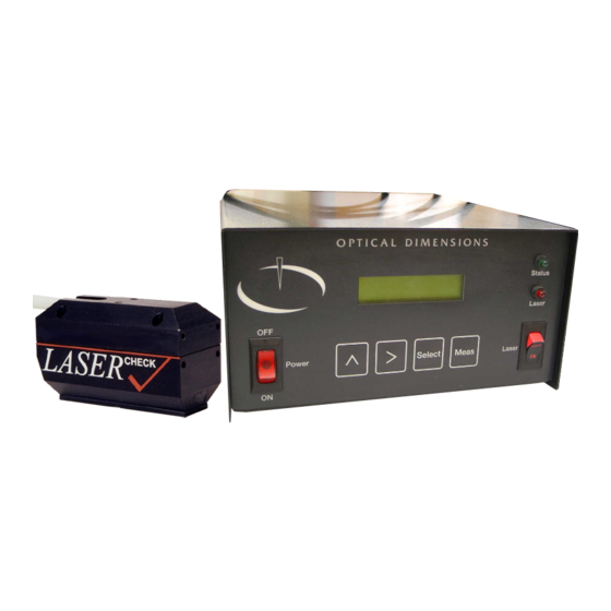
Page 15: Basic Connections Control Box
Basic Connections Control Box OPTICAL DIMENSIONS Input Output Sensor Printer Status RS485 Laser 110/220 VAC > Meas Select RS232 Keyboard Monitor Reset Laser Rear Panel of Box Front Panel of Box Attach the power cable to the “110/220VAC” plug and then connect to 110/220 Volt Power Source. -
Page 16: Physical Mounting
Physical Mounting The Lasercheck head is supplied with a 1/10-inch thick footplate on the bottom. This will align the head within specification on flat surfaces. If surfaces are cylindrical, then optional alignment feet should be used. For surfaces with different geometry, alignment fixturing should be used. An understanding of alignment principals of Lasercheck is required for development of fixturing. -
Page 17: To Install Lasercheck Software
Software Setup Lasercheck uses two different software packages. The control unit has software that initializes electronics, controls the LCD screen, monitors the laser, reads detector signals, and calculates the alignment and surface roughness. It also saves measurements in ASCII format files. This software comes pre-installed inside the control unit. -
Page 18: Basic Operation Using Control Box Pushbuttons
Basic Operation Using Control Box Pushbuttons Once the cables are attached and measurement head is mounted and aligned, you are ready to perform a measurement. Lasercheck is run from the control unit keypad and LCD screen or optionally the Windows software on the host computer. -
Page 19: Lcd Push Buttons
LCD Push Buttons The four push buttons are labeled as following (in the following order left to right) and are for: Switch highlight between options > Scroll through options Select Select highlighted option Meas Take measurement at any time from main or measure windows Highlighting The “^”, “>”, and “Select”... -
Page 20: If Controller Does Not Respond To Pushbuttons
If Controller Does Not Respond to Pushbuttons The automated Lasercheck controller is designed to work under external computer control or under control of the front panel pushbuttons. This is determined by configuration of an internal (user selectable) setup file inside the control box. -
Page 21: Performing Manual Measurements
Performing Manual Measurements The following section covers the minimum basics required to perform measurements. Additional features built into the Lasercheck Windows software are discussed in detail further in the Lasercheck Windows software manual. Choose a Setup File From the Main Screen use the “>” button to select the proper setup file. The controller is delivered with 4 factory provided setup files loaded –... -
Page 22: File Management
File Management File System Window From the Main Window, push the switch (^) push button to highlight the word SYSTEM. Scroll to the word “files” with the scroll (>) push button Push the Select push button. The following screen will be displayed: Manage files: FILES: >Send The file management options available by scrolling are:... -
Page 23: Sending Measurement Data From The Lasercheck Controller
Sending Measurement Data from the Lasercheck Controller Scroll to “FILES: >Send” on the control box with the scroll (>) push button and push the Select push button. The LCD displays the following screen: Sending all data files now. All data files are being transferred to the computer while this is displayed. The receive operation in the windows software should finish automatically when all of the data is received from the controller. -
Page 24: Sending Setup Data With The Windows Software
Sending Setup Data with the Windows Software Start the Lasercheck File Transfer Software by clicking on icon in the Start Menu under “Programs / Lasercheck / Lasercheck File Transfer”. Select the following options if they are not already selected: Com Port: Select the serial port the Lasercheck cable is attached to on your computer Speed:... -
Page 25: Reset Command
Delete all data files? >n/Y Scrolling to highlight “Y” and pushing the Select push button, will delete all data files, then the system will return to the File System Window. Scrolling to highlight “N” and pushing the Select push button will return to the File System Window without deleting files. -
Page 26: Data Files
Data Files: The data files stored in the control box have up to 8 letter file names as prescribed in the setup file. The filename extension is “TXT”. The data files contain measurements and headers. The data fields are separated from the header fields by tab characters so that SPC programs and spreadsheet programs like Excel can read the text files easily. -
Page 27: Advanced Operations
Advanced Operations Operation Using Windows Software The Lasercheck can also be used and controlled through the Lasercheck windows software. The following is an example of using the basic features of the windows software. Control Box Setup Make sure the Lasercheck control box is connected to the computer with the serial null modem cable. For more detail on doing this refer to the “Setting Up the Instrument”... -
Page 28: Setup Options
Setup Options Two parameters should be set prior to creating setup files or performing measurements with the Lasercheck Windows program. 1) Comm Port 2) Automation Type Select the Communications Port Select Setup/Comm Port. Select the communications port that the RS232 null modem cable is connected to on your computer. -
Page 29: Select Automation Types
Select Automation Types Select Setup/Automation Type. Setup for Lab System Check Lab System. Then select “OK”. Lab System Automation will cause Lasercheck to provide single measurements in response to input from the Windows software program or pushbutton on the control box. Setup for Continuous Measurements / Roll Grinding Check “Roll Grinding”. -
Page 30: Set Up For Individual Parts / Parts Inspection
“Roll Grinding” Automation will cause Lasercheck to provide streaming continuous measurements at a rate of approximately 10 Ra values per second in response to input from the Windows software or trigger inputs to the input port of the control box. Continuous measurements are stopped in response to input from the Windows software or trigger inputs to the input port of the control box. - Page 31 Select the “Open Controller Setup” button. A series of pre-installed controller setup files will be presented. 6212A Manual Version 14.56.docx Page 23 of 58...
-
Page 32: Controller Setup Files
Select and open the desired controller setup file. This presents information that will transfer to the Lasercheck controller and define the measurement Controller Setup Files See the Appendix - Setup Files for more information on these files that are integrated into overall Lasercheck setup files. - Page 33 Select and open the desired setup file. This presents similar dialog box to creating a setup file with information that will transfer to the Lasercheck controller and define the measurement 6212A Manual Version 14.56.docx Page 25 of 58...
-
Page 34: Automatic
Automatic Pushing the “Automatic button opens a separate dialog box. Only edit the “Filename Options” button. Manual checkbox setting requires the operator to create a filename whenever a measurement set is complete and ready for saving. Automatic checkbox setting will cause Lasercheck software to automatically create a filename whenever a measurement set is complete and ready for saving. - Page 35 Lasercheck saves files in proprietary format (filename.lsc) that can be later opened, reviewed and printed using Lasercheck software. Checking the “Save ASCII File” checkbox allows a separate ASCII file to be automatically created and specify what elements are contained in that ASCII file. The ASCII file can then be imported into separate compatible programs including Excel spreadsheets for further review.
-
Page 36: Software Manual Operation
Software Manual Operation Perform Measurements Module From the main window of the Lasercheck software select the “Perform Measurements” push-button. This invokes the “setup/open” dialog box. Select a setup file that contained the line “START_INPUT= MEAS”. An information dialog box similar to what is shown during setup file creation will be presented. - Page 37 Select “OK”. The main measurement screen will be presented. 6212A Manual Version 14.56.docx Page 29 of 58...
-
Page 38: Measure Menu
Measure Menu Select the option “Measure”. An empty graph screen with a run menu appears. Note: the following screen may appear. If so, try again and it should work. It may be necessary to reboot software and Lasercheck controller if this persists. 6212A Manual Version 14.56.docx Page 30 of 58... -
Page 39: Start
Start Selecting “Start” from the Run Menu starts the Lasercheck and the graph begins displaying roughness information. A graph of roughness vs. reading number will begin appearing in real time on the screen. In addition, statistics of all measurements will be displayed digitally in real time at the top left and right corners of the graph, and the current measurement in the top center of the graph. -
Page 40: Export
name that is typed in. This data file can be opened for review in the Review Data module from the main screen of the software. Export The Export menu selection will save an ASCII text file of all measurements in the current measurement cycle. This text file will be automatically named “Lasrdata.txt”... - Page 41 appendix section on Lasercheck Alignment Principles and Procedures). Either the surface will move under the gage or the gage will be moved over the surface. In either case, alignment must be maintained during relative motion. An air knife can be used prior to the gage to clean coolant etc. from surfaces to be inspected if necessary.
-
Page 42: Start" And "Stop" Sensor Wiring Inputs
Positioning Prox Sensors on Conveyor for Automated Inspection A “start” sensor should be mounted in a location that activates as soon as the surface to be measured is entering a position for the Lasercheck head to measure (indicated by laser beam being fully positioned at the front edge of the measurement area of the part). -
Page 43: Appendix A - Lasercheck Alignment Principles And Procedures
Appendix A – Lasercheck Alignment Principles and Procedures This section contains information on principals and procedures to install and align Lasercheck heads. The keys to getting accurate and repeatable data are controlling alignment and cleaning the surface. How Does Lasercheck Work? The visible (650-nm.) laser illuminates the surface with a shallow incident angle to measure surface roughness features. -
Page 44: Alignment
Alignment Vertical The specular laser beam must fall on one of detectors 3 to 9 n the 35-element photodiode array. If Lasercheck is too close to the surface, the specular reflection falls on detector number 10 or greater. If Lasercheck is too far from a surface, the specular laser beam falls on detector 2 or smaller, or misses the photodiode array entirely. -
Page 45: Vertical Alignment Base Plate
Vertical Alignment Base plate Lasercheck is shipped with base plate that is pre-aligned to set correct vertical positioning on flat parts. This base will set vertical position of the head so that the specular reflected laser beam will strike close to or on detector 6 in the middle of the detectors 4 to 8. -
Page 46: Horizontal
Horizontal The Lasercheck is also sensitive to horizontal misalignment on curved surfaces. If the Lasercheck Head is correctly aligned, the reflected and scattered laser light reflects back into the center of the detector window. If it is misaligned, the reflected and scattered laser light reflects to one side or the other of the center of the detector window. -
Page 47: Cylindrical Surface Measurement Alignment Fixture
Cylindrical Surface Measurement Alignment Fixture Lasercheck can be equipped with our optional model 6216 spring loaded alignment fixture. This simple to use fixture, when attached to the Lasercheck head will set horizontal position of the head perfectly on cylindrical shaped surfaces ensuring accurate measurements. 6212 on Cylinder Surface with Alignment Fixture Setting Correct Horizontal Position 6212A Manual Version 14.56.docx Page 39 of 58... -
Page 48: Bore Id Surface Measurement Alignment Fixture
Bore ID Surface Measurement Alignment Fixture Lasercheck can be equipped with our optional model YMC070016 bore ID measurement alignment fixture. This mates and centers with a range of bore curvatures setting correct vertical and horizontal position of the head ensuring accurate measurements. The YMC070016 fixture on the 6212 measurement head can be used on any ID bore diameter 2 inches (50 mm) or greater. -
Page 49: Custom Shapes And Fixturing
Custom Shapes and Fixturing 3-Dimensional Shapes 3-Dimensional curvatures and shapes cause Lasercheck to become easily misaligned either in the vertical or horizontal axis. Fixturing must be designed to carefully and repeatably control positioning in both axes so that the specular reflected beam strikes in the middle of the first 11 detectors and the overall reflection falls into the center of the detection window as viewed from the end of the measurement head. -
Page 50: Small Surfaces
Small Surfaces Surfaces that are smaller than the actual footprint of the laser spot (approximately 5 to 6 mm long X 1 mm wide) can be measured. The part of the laser beam that “overfills” the surface can be allowed to pass by. It is important to ensure that part of the beam is not allowed to strike a “secondary”... -
Page 51: Measure/Headtest Dialog Box
Measure/Headtest Dialog Box Measure/Headtest Screen A and B are printed out from our Measure/Headtest selection in our windows software. In this screen, you will see Lasercheck values displayed beside numbers 1 to 37. Numbers 1 to 35 are voltage readings from the 35 array detectors. Also displayed is a sum of voltages from all detectors and a “relative”... -
Page 52: Measure/Headtest Screen B
Measure/Headtest Screen B Measure/Headtest Screen B is a display from a rougher surface. The specular beam is now lost as it bounces off the surface into Lasercheck. There is no obvious large voltage anywhere in the array. The standoff reading indication is no longer reliable. -
Page 53: Measure/Align Dialog Box
Measure/Align Dialog Box Horizontal Alignment with Measure/Align Measure/Align in the windows software will help you with horizontal alignment on cylindrical surfaces. Remember SUM is a sum of all of the voltages from the detectors. When horizontally aligned, you will obtain the largest possible value on Bar Graph and indicated percentage because more light is reflecting into the center of the detector window and detectors. -
Page 54: Verifying Alignment Procedures
Verifying Alignment Procedures Set Head Close Correct Position Horizontal and vertical alignment should be close before performing any alignment with Measure/Headtest or Lasercheck Windows software. If Lasercheck is badly misaligned, than the software cannot locate the specular laser beam for vertical alignment and has little or no signal for horizontal alignment. Align Horizontally Horizontal alignment works best on a clean, rough surface (greater than 10 microinches) with a dominant roughness direction, for example a ground surface. -
Page 55: Appendix B - Mounting/Fixturing Lasercheck
The Lasercheck sensor must be precision adjusted over the surface in 2 axes (X and Z position) for optimal mounting / alignment. Optical Dimensions provides an optional adjustable mounting fixture (model 706200) that provides necessary adjustment of sensor position in an on-line measurement application. -
Page 56: Existing Mounting Holes On Lasercheck Sensor
Existing Mounting Holes on Lasercheck Sensor The CAD image above provides dimensional information for mounting of Lasercheck sensor over a cylindrical surface. IMPORTANT: the position of the measurement sensor relative to the surface is an approximate value. All mounting designs must incorporate fine positioning adjustment of the Lasercheck sensor in the X and Z axis to set correct alignment using Lasercheck software aids. -
Page 57: Appendix C - Setup Files
Appendix C - Setup Files Setup file format RECEIVE_NAME= example.set FILENAME= example START_INPUT= MEAS / SERIAL / EXTERNAL1 RA_UNITS= MICROINCHES / MICRONS RA_LIMITS= 15.00 20.00 LOW_ANALOG= 15.00 HIGH_ANALOG= 20.00 RA_THRESHOLD= 12.00 CAL_TYPE= POWER / EXPONENTIAL CAL1= -11.90 14.81 0.00 0.46 CAL2= 0.00 3.90 2.50... -
Page 58: Ra_Limits
RA_LIMITS This option accepts two numbers; the first is the minimum and the second is the maximum Ra value of the surface specification. This sets the specification range for Ra values. If a measured Ra is outside (lower than the minimum or higher than the maximum) these values pins on the control box output port (Ra_Limit) momentarily close. -
Page 59: Appendix D - Calibration Procedures
Appendix D - Calibration Procedures Theory - Measurement and Calibration Measurement of Roughness Lasercheck technology is based on measuring change in properties of a laser beam reflecting from a surface. When a laser is shone on a perfectly smooth mirror like surface there will be a clean “specular” laser reflection off that surface. -
Page 60: Requirement For Calibration Of Lasercheck To Specific Machining Operation
2) A sand blasting operation creates a roughness pattern on a surface that is non-directional or isotropic. This non-directional roughness pattern generates a scattered light reflection pattern that is also non- directional, visually appearing like a 3D “cone” of scattered light. There are other examples of unique surface roughness pattern from various machining operations (swirl pattern, repeating groves, random / fractal, predominant peaks, predominant valleys) that uniquely affect the shape of the scattered light pattern. -
Page 61: Base Calibration
Lasercheck will measure different signals and calculate different roughness for these two surfaces with identical Ra. The surface roughness pattern (machining operation) and resulting scatter pattern therefore must be an integral part of any Lasercheck calibration. Base Calibration Lasercheck is shipped calibrated to traceable standards for measurement of directional ground and sanded surfaces. -
Page 62: Appendix E - Input And Output Pinouts
Appendix E – Input and Output Pinouts Input: 9-Pin Female D-sub Connector Internal Opto relay: Pin 1, 6, 2 = Opto relay 1, 2, 3 Optically Isolated. Must be connected to power (can use control box voltage – Pin 9). Pulls low to activate. -
Page 63: Internal Opto Relay Schematic
Internal Opto relay Schematic: Opto Supply Pin Optical Relay Activates with Input Trigger Input Trigger Typical Wiring Example: 1) Using Unpowered Switches for inputs: a) Connect Power for Opto relays using Control Box Voltage (Pin 9) Opto Supply 1 (Pin 1) Opto Supply 2 (Pin 6) Opto Supply 3 (Pin 2) +Voltage (Pin 9) -
Page 64: Using Powered Triggering Device (E.g. Proximity Sensors) For Inputs
2) Using Powered Triggering Device (e.g. Proximity Sensors) for Inputs: a) Connect Power for Opto relays and for Triggering Devices using Control Box Voltage (Pin 9) b) Connect Triggering Devices between Ground (Pin 7) and Input Pin Recommended Proximity Sensor Specifications: ... -
Page 65: Output: 9-Pin Female D-Sub Connector
Output: 9-Pin Female D-sub Connector Failed part output. Closes when measurement is out of software specified range. SPDT Relay, Resistive load Max: 200mA Max Ratings: 30VDC @ 1A, 125VAC @ 0.1A Internal parts: Omron G6E, connected internally with 28AWG ribbon cable Signal Analog_Out + (0-10V / 4-20mA) Not Used... -
Page 66: Output Schematic Analog_Out
2) Output Schematic Analog_Out a) 0-10V Pin 1 0 Volt @ LOW_ANALOG 10 Volts @ HIGH_ANALOG Pin 6 b) 4-20mA Pin 1 9 to 24 Volt EXTERNAL Power Source 4 milliamp @ LOW_ANALOG 20 milliamp @ Pin 6 HIGH_ANALOG NOTE: 9 to 24 Volt power must be connected in series with Current Monitor (Must be External power source): 6212A Manual Version 14.56.docx Page 58 of 58...
Need help?
Do you have a question about the LASER CHECK 6212A and is the answer not in the manual?
Questions and answers