Table of Contents
Advertisement
Quick Links
Advertisement
Table of Contents

Related Manuals for Optical dimensions Lasercheck 6212C


Summary of Contents for Optical dimensions Lasercheck 6212C
- Page 1 OPTICAL DIMENSIONS™ 2973 Harbor Blvd, #665, Costa Mesa, CA 92626 Phone: (831) 287-0495 i n f o @ o p t i c a - l d i m e n s i o n s . c o m w w w .
-
Page 2: Operations And Specification Manual For The
Dimensions. The information in this document is provided as an aid in the Assembly, Diagnostics, and Operation of the Lasercheck Gage, Components, and Accessories and is not to be used otherwise or reproduced without written consent of Optical Dimensions. The Lasercheck gage is patented technology protected under US Patent Number 5,608,527. -
Page 3: Table Of Contents
Electrical ....................................2 Laser ......................................2 WARRANTY OVERVIEW ............................... 3 LIMITATION OF WARRANTY ..............................3 Contact Optical Dimensions customer service for shipping instructions: ................3 MAINTENANCE ..................................4 Cleaning the Windows ................................4 Assistance ....................................4 INTRODUCTION TO LASERCHECK ............................5 Overview.................................... - Page 4 OPTICAL DIMENSIONS™ 2973 Harbor Blvd, #665, Costa Mesa, CA 92626 Phone: (831) 287-0495 i n f o @ o p t i c a - l d i m e n s i o n s . c o m w w w .
- Page 5 OPTICAL DIMENSIONS™ 2973 Harbor Blvd, #665, Costa Mesa, CA 92626 Phone: (831) 287-0495 i n f o @ o p t i c a - l d i m e n s i o n s . c o m w w w .
- Page 6 OPTICAL DIMENSIONS™ 2973 Harbor Blvd, #665, Costa Mesa, CA 92626 Phone: (831) 287-0495 i n f o @ o p t i c a - l d i m e n s i o n s . c o m w w w .
-
Page 7: Performance Specifications
PERFORMANCE SPECIFICATIONS Measurement / Detection Method Angle resolved laser scattering Measurement speed Single measurement in < 0.5 seconds Measurement range 0.5 µinch to 40 µinch / 0.0125 µm to 1.0 µm Repeatability ± 3.0% of measured value Spot size (area-measured) 5 mm X 1 mm Environmental considerations (temperature / humidity): Operating... -
Page 8: Safety
SAFETY Electrical Lasercheck has been designed as a sealed and enclosed system. Voltages to operate the measurement sensor are low (0 to +5 Volts) to minimize shock hazard. Laser The laser used in Lasercheck is a class II laser device. Class II lasers are not considered hazardous to the skin but are considered a “chronic viewing hazard”. -
Page 9: Warranty Overview
The Lasercheck system has a warranty period of one (1) year from date of first usage. This warranty is against defects in material and workmanship. During the warranty period, Optical Dimensions will, at its option, either repair or replace products, which prove to be defective. For detailed warranty information, refer to second page of this manual. -
Page 10: Maintenance
Lasercheck housing and electronics are well grounded. The head is sealed at all seams and holes to protect components from external contaminants. The user should not open the measurement head. If opened by non- authorized personnel, the warranty provided by Optical Dimensions will be void. Cleaning the Windows The internal optics and electronics are cleaned during assembly and kept within the sealed sensor. -
Page 11: Introduction To Lasercheck
INTRODUCTION TO LASERCHECK Overview Lasercheck is designed to perform high speed, repeatable, non-contact measurements of surface roughness. A built in visible laser diode emits a laser beam from the bottom of the gage illuminating the surface beneath it. After striking the surface, the laser light is reflected and scattered back into the Lasercheck detection system. The overall intensity and distribution of the reflected and scattered light is measured, digitized by Lasercheck electronics, and then Ra roughness is calculated for the illuminated area. -
Page 12: Setting Up The Instrument
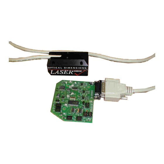
Setting up the Instrument Unpacking Lasercheck All components of Lasercheck have been inspected and tested individually and as a system before shipping. You should find the following items with your system: 1) Lasercheck measurement head. 2) Standoff (0.100”) plate (typically attached to measurement head) 3) Lasercheck control board 4) Wire harnesses, bare at one end, connector for serial and power to board at other end 5) CD or USB Memory Stick with Lasercheck Software Calibration &... -
Page 13: Basic Connections
Basic Connections The control board has a DB15 connector at the top which mates to the connector end of the measurement head cable. The cable should be secured with the thumbscrews on the cable. The control board has several 6-position connectors labeled J1 through J7. Connections for basic functions are described below. -
Page 14: J3 And J4 Power Connections
J3 and J4 Power Connections The control board also has 2 power connectors, J3 and J4, which are powered by 7 to 18 volts DC at 100 mA. Pin 2 and Pin 3 both should be powered. Pin 2 is the main power to the board. Pin 3 powers a transistor switch providing other functions and 5 VDC to the board. -
Page 15: Basic Operation
Protocol” in this manual) to the serial connection pins on the control board. The control board responds to these specific requests with measurement results to the same serial connection pins. Following is an abbreviated description for setup and alignment of a Lasercheck 6212C system and performance of a typical measurement. Software Setup The control board has software pre-loaded that initializes electronics, monitors the laser, reads detector signals, and calculates the alignment and surface roughness. -
Page 16: Turn On Lasercheck Windows Software
Turn on Lasercheck Windows Software The LaserCheckVersion5.exe program was designed for advanced Lasercheck systems. It operates in a limited function with the 6212C system allowing initial testing. It will be installed in “C:\Program Files (x86)\Lasercheck 6212C\Lasercheck Program” folder. Running the program will bring up the main screen as follows: Set Comm Port on computer Select the “Setup”... -
Page 17: Review Or Create Lasercheck Setup Files On Computer
Select “Setup\Comm Port” and the following dialog box will appear: Select the appropriate comm. port on your computer and select “OK”. Review or Create Lasercheck Setup Files on computer Select “Setup\Setup” and the following dialog box will appear: 6212C Manual Version 15_22 Rev 07-19.docx Page 11 of 53... -
Page 18: Perform Measurements
When Lasercheck software is first installed on your computer, one or two sample setup files (*.STP) are loaded on your computer and will appear under the “C:\ProgramData\Lasercheck 6212C Files\Setup” directory. Navigate to this directory. You can open, review, edit, create new setup files and save them to this directory. - Page 19 Navigate to this directory. For use with the 6212C Lasercheck system, select the “manual.stp” file. The following dialog box will appear: If it is not the correct setup file select the “Cancel” push-button. This will return you to the “Main Measurement Window”...
- Page 20 Lasercheck system. For a more detailed description of this software please refer to included archive “Lasercheck Windows Software Manual V1_6_1”. Test measurements can be saved to “C:\ProgramData\Lasercheck 6212C Files\Data” directory for review in the Review Data module found in the main startup screen.
-
Page 21: Physical Mounting
Physical Mounting Manual Operation The hand held version of the Lasercheck head is supplied with base plate on the bottom. This will align the head within specification on flat surfaces. If surfaces are cylindrical, then optional alignment feet should be used. For surfaces with different geometry, alignment fixturing should be used. -
Page 22: Numerous Continuous Measurements
Numerous Continuous Measurements Trigger Sensors Lasercheck Sensor Air Knife Surface Direction Rotation Lasercheck Sensor Mounted on Large Rotating Roll for Automated Continuous Inspection Trigger Sensors Lasercheck Sensor Surface Direction Large Continuous Flat Surface Air Knife Lasercheck Sensor Mounted on Large Flat Sheet for Automated Continuous Inspection Lasercheck Head Mounted over Large Surface s for Continuous Automated Inspection There are ten drilled and tapped holes on the Lasercheck sensor head that can be used for mounting and installing the Lasercheck in a continuous automated inspection application. -
Page 23: Individual Parts / Parts Inspection
Individual Parts / Parts Inspection Lasercheck Sensor Air Knife “Proxy Sensors Parts Parts Conveyor Lasercheck Sensor Mounted on Conveyor for Automated Single Measure Inspection Figure 3 – Lasercheck Head Mounted on Conveyor for Automated Inspection There are ten drilled and tapped holes on the Lasercheck sensor head that can be used for mounting and installing the Lasercheck in an automated inspection application. -
Page 24: Setup And Alignment
A “start” sensor should be mounted in a location that activates as soon as the surface to be measured is entering a position for the Lasercheck head to measure (indicated by laser beam being fully positioned at the front edge of the measurement area of the part). Setup and Alignment Lasercheck head alignment is critical to accurate and repeatable Lasercheck measurements. - Page 25 Detector Voltage HORIZONTAL ALIGNMENT VALUE = 4.609 Lasercheck Alignment Data Sample Alignment Aid Graph 6212C Manual Version 15_22 Rev 07-19.docx Page 19 of 53...
-
Page 26: Performing Roughness Measurements
Performing Roughness Measurements Message Type 02 Message Type 02 returns a “rough Ra value”, “smooth Ra value”, “error code”, and “max detector”. Rough and Smooth Ra Value Lasercheck uses two different calculation routines to calculate roughness. One routine is optimized and slightly more accurate for “relatively smooth”... - Page 27 There are very few surfaces or conditions that would produce such a low value. This should be interpreted as possible problem with Lasercheck electronics, gross misalignment, or poor cable connections. As a reference, Lasercheck should return values of several volts for the sum_voltage values on steel or aluminum surfaces that have been turned, ground or similarly finished.
-
Page 28: Appendix A - Lasercheck Alignment Principles And Procedures
Appendix A – Lasercheck Alignment Principles and Procedures This section contains information on principals and procedures to install and align Lasercheck heads. The keys to getting accurate and repeatable data are controlling alignment and cleaning the surface. How Does Lasercheck Work? The visible (650-nm.) laser illuminates the surface with a shallow incident angle to measure surface roughness features. -
Page 29: Alignment
Alignment Vertical The specular laser beam must fall on one of detectors 3 to 9 n the 35-element photodiode array. If Lasercheck is too close to the surface, the specular reflection falls on detector number 10 or greater. If Lasercheck is too far from a surface, the specular laser beam falls on detector 2 or smaller, or misses the photodiode array entirely. -
Page 30: Vertical Alignment Base Plate
Vertical Alignment Base plate Lasercheck is shipped with base plate that is pre-aligned to set correct vertical positioning on flat parts. This base will set vertical position of the head so that the specular reflected laser beam will strike close to or on detector 6 in the middle of the detectors 4 to 8. -
Page 31: Horizontal
Horizontal The Lasercheck is also sensitive to horizontal misalignment on curved surfaces. If the Lasercheck Head is correctly aligned, the reflected and scattered laser light reflects back into the center of the detector window. If it is misaligned, the reflected and scattered laser light reflects to one side or the other of the center of the detector window. -
Page 32: Cylindrical Surface Measurement Alignment Fixture
Cylindrical Surface Measurement Alignment Fixture Lasercheck can be equipped with our optional model 6216 spring loaded alignment fixture. This simple to use fixture, when attached to the Lasercheck head will set horizontal position of the head perfectly on cylindrical shaped surfaces ensuring accurate measurements. 6212 on Cylinder Surface with Alignment Fixture Setting Correct Horizontal Position 6212C Manual Version 15_22 Rev 07-19.docx Page 26 of 53... -
Page 33: Bore Id Surface Measurement Alignment Fixture
Bore ID Surface Measurement Alignment Fixture Lasercheck can be equipped with our optional model YMC070016 bore ID measurement alignment fixture. This mates and centers with a range of bore curvatures setting correct vertical and horizontal position of the head ensuring accurate measurements. The YMC070016 fixture on the 6212 measurement head can be used on any ID bore diameter 2 inches (50 mm) or greater. -
Page 34: Custom Shapes And Fixturing
Custom Shapes and Fixturing 3-Dimensional Shapes 3-Dimensional curvatures and shapes cause Lasercheck to become easily misaligned either in the vertical or horizontal axis. Fixturing must be designed to carefully and repeatably control positioning in both axes so that the specular reflected beam strikes in the middle of the first 11 detectors and the overall reflection falls into the center of the detection window as viewed from the end of the measurement head. -
Page 35: Small Surfaces
Small Surfaces Surfaces that are smaller than the actual footprint of the laser spot (approximately 5 to 6 mm long X 1 mm wide) can be measured. The part of the laser beam that “overfills” the surface can be allowed to pass by. It is important to ensure that part of the beam is not allowed to strike a “secondary”... -
Page 36: Checking Alignment Using The Lasercheck Diagnostics Option
Checking Alignment Using the Lasercheck Diagnostics Option 1) Prepare Software to Receive Alignment Measurement Turn on terminal program such as HyperTerminal, or software you have developed to communicate with Lasercheck board. Prepare for execution of Message Type 15 to the Lasercheck board. 2) Prepare Sample and Fixture Set the measurement head on the part (or put the part on the fixture or measurement head) 3) Perform Measurement... -
Page 37: Save Measurement Data For Input To Lasercheck Align Graph.xls Spreadsheet
0.0040 0.0036 0.0036 0.0022 0.0025 0.0026 0.0025 0.0020 sum_voltages,01.0013 Ra,00.6534,00.8867,ok Sums,00.5849,00.5240 Sum3,07,00.4029 MaxD,06,0.1502 4) Save Measurement Data for Input to Lasercheck Align Graph.xls Spreadsheet Save the data to the filename “laseralign.txt” in the directory “C:\Program Files\Lasercheck” created by the installation program. Only this filename and directory will import correctly into the spreadsheet. 5) Graphing the Lasercheck Data Measurements in Excel Spreadsheet The alignment measurement can now be graphed for visual display in the included Excel spreadsheet. -
Page 38: Determining Alignment Using The Lasercheck Alignment Graph Excel Spreadsheet
Detector Voltage HORIZONTAL ALIGNMENT VALUE = 5.575 Lasercheck Alignment Data Typical Spreadsheet Alignment Curve Showing Specular Centered on Detector 7 5) Determining Alignment using the Lasercheck Alignment Graph Excel Spreadsheet Vertical Alignment The Vertical portion of the alignment graph is a horizontal bar graph representing relative voltages from all of the 35 detectors. -
Page 39: Notes To Using The Lasercheck Diagnostics Option For Alignment
measurements while incrementally adjusting horizontal position with fixturing to determine the highest possible value for that part. Once that highest value has been achieved, then the fixture should be secured at that location. You must be sure to pass the head back and forth over the surface one or two times so that the maximum possible value for sum_voltage can be found. -
Page 40: Horizontal Alignment
On these rougher surfaces, we cannot do height alignment with Laserchecks' help. What must be done is to either align on a smooth surface in the exact position the rough surface is at or make the rough surface look smooth to Lasercheck for just the alignment. A reliable way to make a rough surface look smooth to Lasercheck is to wipe a thin film of oil on the surface. -
Page 41: Verify Alignment
Verify Alignment Check visually and with software that horizontal alignment has not changed during the process of performing vertical alignment. As surfaces get rougher (greater than 20 microinches), resolution of Lasercheck decreases and sensitivity to misalignment increases. Mounting and alignment stability becomes more important to maintaining high repeatability from Lasercheck. -
Page 42: Appendix B - Mounting/Fixturing Lasercheck
The Lasercheck sensor must be precision adjusted over the surface in 2 axes (X and Z position) for optimal mounting / alignment. Optical Dimensions provides an optional adjustable mounting fixture (model 706200) that provides necessary adjustment of sensor position in an on-line measurement application. -
Page 43: Existing Mounting Holes On Lasercheck Sensor
Existing Mounting Holes on Lasercheck Sensor The CAD image above provides dimensional information for mounting of Lasercheck sensor over a cylindrical surface. IMPORTANT: the position of the measurement sensor relative to the surface is an approximate value. All mounting designs must incorporate fine positioning adjustment of the Lasercheck sensor in the X and Z axis to set correct alignment using Lasercheck software aids. -
Page 44: Appendix C - Calibration Procedures
Appendix C - Calibration Procedures Theory - Measurement and Calibration Measurement of Roughness Lasercheck technology is based on measuring change in properties of a laser beam reflecting from a surface. When a laser is shone on a perfectly smooth mirror like surface there will be a clean “specular” laser reflection off that surface. -
Page 45: Requirement For Calibration Of Lasercheck To Specific Machining Operation
There are other examples of unique surface roughness pattern from various machining operations (swirl pattern, repeating groves, random / fractal, predominant peaks, predominant valleys) that uniquely affect the shape of the scattered light pattern. Within any machining operation, as surface roughness increases, the specular portion of reflection decreases in intensity and the scatter portion of reflection increases in intensity. -
Page 46: Base Calibration
Base Calibration Lasercheck is shipped calibrated to traceable standards for measurement of directional ground and sanded surfaces. Lasercheck can be calibrated for other surface finishing processes using an Excel spreadsheet calibration tool provided to generate a machining / surface pattern specific calibration file. Overview of Calibration Process Calibration of the Lasercheck gage involves customer testing known surfaces with the Lasercheck. -
Page 47: Appendix D - Communication Protocol
Appendix D – Communication Protocol The AD board has a PIC processor that communicates thru a serial port on J1 or J2. J1 is a 5 volt buffered port for integration into a portable unit. J2 is for communication to a standard PC com port. Communications for both will be at 57600 baud, 8N1. -
Page 48: Message Types
Message Types: @02 Request Ra Value @02#<cr-lf> Returns a single @02 response. If continuous mode was running, it now quits Response @02,00.1234,01.1234,ok,dd,12.3456,#<cr-lf> Ra rough, Ra smooth, Error Code, Max Detector, Sum Voltage of Detectors 1-37 @02,00#<cr-lf> Returns continuous @02 response. Will continue making measurements until a @02#<cr-lf>... -
Page 49: Request Ra Value
or – for detector “out of range”. Occurs if error in defining detectors in configuration file lv – for possible too low sum_voltages for reliable Ra calculation (less than 100 mVolts) rr - for rough "range error". Occurs if error in defining detectors in configuration file Note: it is important to interpret the “tc”... -
Page 50: Response Details
Ra rough, Ra smooth, Error Code, Max Detector, Sum Voltage of Detectors 1-37 @03,dd#<cr-lf> Returns continuous stream of Ra values when the start input pin is in the trigger state until "dd" number of measurements have occurred (dd = 01 to 99). When the start trigger goes inactive, the Ra stream will stop. -
Page 51: 04#
max_detector is the integer value of the detector with the maximum voltage on it. This value will always be 2 digits and can range from 01 to 35. The location of the maximum detector voltage is useful for determining vertical alignment on smooth surfaces only. Refer to the alignment section in the manual. sum_voltages is the sum of all voltages from detectors 01 to 35.Specular Values Request -
Page 52: Response Details
@05,01#<cr-lf> Returns average of all Ra values from when the start input pin is activated until stop input pin is activated. Response @05,000.1234,001.1234,ok,dd,12.3456,#<cr-lf> When the stop input is activated after a start input, a single Ra value representing average of all will be sent. Ra rough, Ra smooth, Error Code, Max Detector, Sum Voltage of Detectors 1-37 Response Details: The response from the interconnect board will be the rough then the smooth roughness values. -
Page 53: Set Xx Subfunctions
Activate Failed Part Output Options Set Values xx = subfunction Request Values @07#<cr-lf> Response @07<cr-lf> Set xx subfunctions @07,xx#<cr-lf> Turn off failed part output. Any value above max roughness or below min roughness encountered between start and stop, contact closes after stop received All values above max roughness or below min roughness encountered during start and stop, contact closes and opens with bad and good values Average value above max roughness or below min roughness encountered between start and... -
Page 54: 15
@15<cr-lf> Combine Cmd 11, 02, and 04 Response: @15<cr-lf> Resp 11 0.123456<cr-lf> Detector 1 volts 0.123456<cr-lf> Detector 2 volts Same for Detectors 3-37 Detector 3-37 volts 12.3456<cr-lf> Sum Voltage of Detectors 1-37 Resp 02 00.1234,01.1234,ok,dd,12.3456<cr-lf> Ra rough, Ra smooth, Error Code, Max Detector, Sum Voltage of Detectors 1-37 Resp 04 00.1234,00.1234<cr-lf>...Combine Cmd 11, 02, And 04 -
Page 55: 22,Xx,Vvv#
@22,xx,vvv#<cr-lf> Set/Query Configuration Values Set Values xx = subfunction vvv = subfunction value Sub Command details: xx subfunction Default 01,LIMIT_LOW, set min roughness LIMIT_LOW, set min roughness value for failed part value output 02,Laser Settling Laser Settling 55.56uS Steps 03,Head Mux Settling Ext.Set/Query Configuration Values -
Page 56: 23,Xxxxx#
@23,xxxxx#<cr-lf>, Set/Query Head Serial Number Note: Factory Set Set Command: @23,xxxxx#<cr-lf>, Set/Query Head Serial Number Query Command: @23#<cr-lf> Query Response: @23,C11xxxxx,#<cr-lf> @26,b,xxx.xxV#<cr-lf>, Set/Query resistor values Note: Factory Set Set command: @26,b,xxx.xxV#<cr-lf> b is the Bank Number. Range is 1-5. xxx.xx is the resistor value. Default is 1.0K. V is the multiplier, either K for kilohm or M for Megohm., Set/Query Head Serial Number -
Page 57: 29,Xx,Vv.vv#
@29,xx,vv.vv#<cr-lf> Set/Query Ra Calibration Values Set command: @29,xxxxx,wwwww.wwwww#<cr-lf> xxxxxx is alpha/numeric up to 6 character parameter NAME,UNITS,THRESH,A1,B1,C1,BP1,A2,B2,C2,BP2,A3,B3,C3, wwwww.wwwww is the alpha/numeric up to 11-chacter value 2 decimal place precision. A Minus sign is optional. Example: Set A1 to -11.90, B1 to 14.81, C1 to 0.00, and BP! To 0.46 (as in 6212Gd file) @29,A1,-11.90#<cr-lf>...Set/Query Ra Calibration Values -
Page 58: Appendix E - Wiring And Dimensions American And Metric Versions
Appendix E – Wiring and Dimensions American and Metric Versions 6212C Manual Version 15_22 Rev 07-19.docx Page 52 of 53... - Page 59 6212C Manual Version 15_22 Rev 07-19.docx Page 53 of 53...