Sign In
Upload
Manuals
Brands
Optical dimensions Manuals
Measuring Instruments
LASER CHECK 6212A
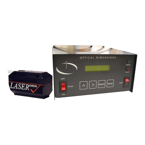
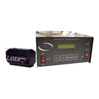
Optical dimensions LASER CHECK 6212A Manuals
Manuals and User Guides for Optical dimensions LASER CHECK 6212A. We have
1
Optical dimensions LASER CHECK 6212A manual available for free PDF download: Manual
Optical dimensions LASER CHECK 6212A Manual (66 pages)
Brand:
Optical dimensions
| Category:
Measuring Instruments
| Size: 3.25 MB
Table of Contents
Operations and Specification Manual for the
2
Lasercheck 6212A System
2
Revision 14.56
2
Optical Dimensions
2
Table of Contents
3
Performance Specifications
9
Other Features
9
Safety
10
Electrical
10
Laser
10
Warranty Overview
11
Limitation of Warranty
11
Contact Optical Dimensions Customer Service for Shipping Instructions
11
Maintenance
12
Cleaning the Windows
12
Assistance
12
Introduction to Lasercheck
13
Overview
13
Setting up the Instrument
14
Unpacking Lasercheck
14
Basic Connections Control Box
15
Physical Mounting
16
Mounting/Fixturing Lasercheck
16
To Install Lasercheck Software
17
Basic Operation Using Control Box Pushbuttons
18
Turning the System on
18
Main Screen
18
Control Unit and Displays
18
LCD Screen
18
LCD Push Buttons
19
Highlighting
19
If Controller Does Not Respond to Pushbuttons
20
Performing Manual Measurements
21
Choose a Setup File
21
Measure Window with Results
21
Saving a Measurement
21
File Management
22
File System Window
22
Send Command
22
Preparing Windows Software to Receive Files
22
Sending Measurement Data from the Lasercheck Controller
23
Receive Command
23
File Naming
23
Preparing Control Box to Receive Files
23
Sending Setup Data with the Windows Software
24
New Cal Command
24
Delete Command
24
Reset Command
25
Exit Command
25
Data Files
26
Sample Data File
26
Advanced Operations
27
Operation Using Windows Software
27
Control Box Setup
27
Starting Windows Software
27
Entering the Setup Module
27
Setup Options
28
Select the Communications Port
28
Select Automation Types
29
Setup for Lab System
29
Setup for Continuous Measurements / Roll Grinding
29
Set up for Individual Parts / Parts Inspection
30
Create New Lasercheck Windows Setup Files
30
Controller Setup Files
32
Creating Controller Setup Files
32
Open Lasercheck Windows Setup Files
32
Automatic
34
Save Parameters
34
Software Manual Operation
36
Perform Measurements Module
36
Measure Menu
38
Start
39
Stop
39
Sequence
39
Save
39
Export
40
Return
40
Automated Operation
40
Start" and "Stop" Sensor Wiring Inputs
42
Appendix A - Lasercheck Alignment Principles and Procedures
43
How Does Lasercheck Work
43
Alignment
44
Vertical
44
Vertical Alignment Base Plate
45
Horizontal
46
Cylindrical Surface Measurement Alignment Fixture
47
Bore ID Surface Measurement Alignment Fixture
48
Directional / Rotational
48
Custom Shapes and Fixturing
49
3-Dimensional Shapes
49
Small Surfaces
50
Measure/Headtest Dialog Box
51
Measure/Headtest Screen a
51
Measure/Headtest Screen B
52
Measure/Align Dialog Box
53
Horizontal Alignment with Measure/Align
53
Verifying Alignment Procedures
54
Set Head Close Correct Position
54
Align Horizontally
54
Align Vertically
54
Verify Alignment
54
Appendix B - Mounting/Fixturing Lasercheck
55
Existing Mounting Holes on Lasercheck Sensor
56
Appendix C - Setup Files
57
Setup File Format
57
Receive_Name
57
Filename
57
Start_Input
57
Meas
57
Serial
57
External1
57
Ra_Units
57
Ra_Limits
58
Analog_Output
58
Low_Analog
58
High_Analog
58
Jumper Settings for Setting Analog Output to 4-20 Ma or 0-10 V
58
Ra_Threshold
58
Cal_Type
58
Calibration
58
Default.set Setup Files
58
Appendix D - Calibration Procedures
59
Theory - Measurement and Calibration
59
Measurement of Roughness
59
Requirement for Calibration of Lasercheck to Specific Machining Operation
60
Base Calibration
61
Overview of Calibration Process
61
Appendix E - Input and Output Pinouts
62
Input: 9-Pin Female D-Sub Connector
62
Internal Opto Relay
62
Trigger Pins
62
Power Pins
62
Internal Opto Relay Schematic
63
Typical Wiring Example
63
Using Unpowered Switches for Inputs
63
Using Powered Triggering Device (E.g. Proximity Sensors) for Inputs
64
Recommended Proximity Sensor Specifications
64
Output: 9-Pin Female D-Sub Connector
65
Output Schematic Ra_Limit
65
A) Normal State - Surface Within Ra_Limit - in Spec
65
B) Surface Outside Ra_Limit - out of Spec
65
Output Schematic Analog_Out
66
Advertisement
Advertisement
Related Products
Optical dimensions Lasercheck 6212C
Optical dimensions LASER 5872C
Optical dimensions Categories
Measuring Instruments
More Optical dimensions Manuals
Login
Sign In
OR
Sign in with Facebook
Sign in with Google
Upload manual
Upload from disk
Upload from URL