Advertisement
Quick Links
INSTRUCTION AND SECURITY
MANUAL
BOARD LIFTER
READ THIS MANUAL CAREFULLY BEFORE THE FIRST USE
• Respect the safety instructions in order to avoid injuries or damages on surrounding elements.
• Follow the operating instructions to avoid damaging the tool.
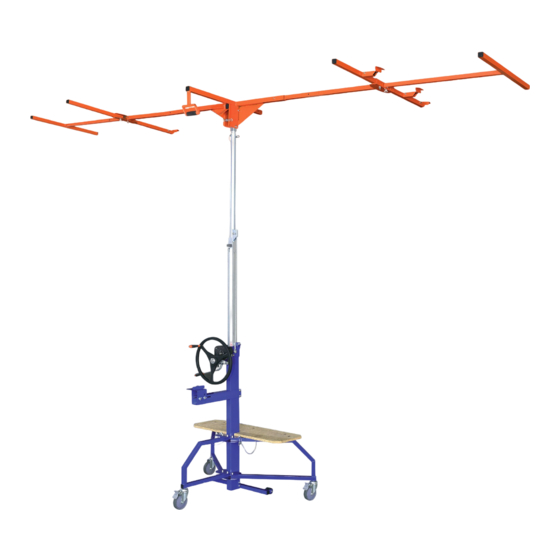
HANDLE TO ANGLE
THE TOP RACK
SAFETY BRAKE
STEERING WHEEL
HANDLE
MAIN BRAKE LEVER
POWER DRILL
SUPPORT BASE
CLAMPING
SCREW
LEVER
WOODEN PLATFORM
SPECIFICATIONS
Reference : 267455
Maximum loading weight : 80 kg (175 lbs)
Maximum board dimensions : 1,20 x 6.00 m (3,94 x 19,69 Ft)
Minimum board dimensions : 0.15 x 0.60 m (0.49 x 1.97 Ft)
Maximum height with extension part : 4,50 m (14,76 Ft)
Maximum height without extension part : 3,50 m (11,48 Ft)
Minimum height : 161 cm (5,28 Ft)
Maximum vertical lifting height with 2,50 m (8,2 Ft) height board :5,75 m (18,86 Ft)
Board loading height : 80 cm (2,62 Ft) without extension
Minimum width in moving/storage position : 63 cm (24
Total gross weight: 68.5 kg (151 lbs)
WEAR PARTS
Ref 526730 - Brake lining
Ref 526731 - Metallic cable
Ref 526733 - Wheel with brake
Ref 526734 - Wheel without brake
- Ref 526732 - Hex bit for using with power drill
- Ref 526761 - Steering wheel central screw
- Ref 526735 - Top rack retractable stopper
- Ref 526756 - Steering wheel
- Ref 526740 - Steering wheel handle
- Ref 526746 - Main brake lever
- Ref 526747- Removable pin
- Ref 526741 - Balance bar with wheels
- Ref 526742 - Power drill support base
- Ref 526737 - Middle foot
- Ref 526744 - Side foot with brake
- Ref 526743 - Side foot without brake
- Ref 526763 - Top rack
- Ref 526764 - Right arm
- Ref 526765 - Left arm
REMOVABLE
- Ref 526766 - T-arm tube
PIN
- Ref 526757 - Extension tube
- Ref 526758 - Internal tube
- Ref 526736 - Wooden platform
- Ref 526754 - 43 mm (1
- Ref 526753 - 58 mm (2
- Ref 526751 - 68 mm (2
- Ref 526750 - 78 mm (3
- Ref 526755 - Nut
Ref. 267455
")
3/4
SPARE PARTS
) screw + nut
3/4''
) screw + nut
1/4''
) screw + nut
5/8''
) screw + nut
1/8''
Advertisement

Subscribe to Our Youtube Channel
Related Manuals for EDMA EDMAPLAC MEGA

Summary of Contents for EDMA EDMAPLAC MEGA
- Page 1 INSTRUCTION AND SECURITY Ref. 267455 MANUAL BOARD LIFTER READ THIS MANUAL CAREFULLY BEFORE THE FIRST USE • Respect the safety instructions in order to avoid injuries or damages on surrounding elements. • Follow the operating instructions to avoid damaging the tool. HANDLE TO ANGLE THE TOP RACK SPECIFICATIONS...
- Page 2 INSTRUCTION AND MAJ - 05/18 SECURITY MANUAL Ref. 267455 ® EDMAPLAC MEGA ASSEMBLY INSTRUCTIONS NECESSARY TOOLS : 13 mm (1/2”) flat wrench, 6 mm (1/4”) hex wrench T-Arms tubes Top rack Arms Main body Integrated extension Support base power drill...
- Page 3 INSTRUCTION AND MAJ - 05/18 SECURITY MANUAL Ref. 267455 Insert the 1 m (3,28 Ft) extension in the frame and lock it in the selected hole with the removable pin. The extension has 3 different height positions : 3,50 m (11,48 Ft), 4 m (13,12 Ft) and 4,50 m (14,76 Ft).
- Page 4 INSTRUCTION AND MAJ - 05/18 SECURITY MANUAL Ref. 267455 OPERATING INSTRUCTIONS Lift the latch to unlock the top rack and tilt it completely. Insert the arms in the tube according to the selected setting, the retractable pin must be locked in the hole. Block the 2 wheel brakes, then load the board.
- Page 5 INSTRUCTION AND MAJ - 05/18 SECURITY MANUAL Ref. 267455 OPERATING INSTRUCTIONS Unlock the 2 wheel brakes and turn the steering wheel while pushing the main brake lever to lift the board. Once the board touches the ceiling, position the board perfectly and lock the wheel brakes while screwing the board.
-
Page 6: Loading Configurations
INSTRUCTION AND MAJ - 05/18 SECURITY MANUAL Ref. 267455 LOADING CONFIGURATIONS HORIZONTAL CEILING - SLOPING CEILING AND HORIZONTAL WALL SETTING Open the feet as much as possible and insert each removable pin in the 3rd hole of the base frame. Insert arms horizontal... - Page 7 INSTRUCTION AND MAJ - 05/18 SECURITY MANUAL Ref. 267455 LOADING CONFIGURATIONS VERTICAL LIFTING AND VERTICAL SLOPING CEILING SETTING Insert the arms in the vertical tubes, the retractable pin must be locked in the selected hole according to the board dimensions. - 1st hole for vertical sloping ceiling hole (with...
- Page 8 INSTRUCTION AND MAJ - 05/18 SECURITY MANUAL Ref. 267455 AUTOMATIC USE ASSISTED BY POWER DRILL First of all, you must use the power drill support base for safety reason. Then, set up the EDMAPLAC MEGA ® according to the selected setting configuration. Adjust power drill...
-
Page 9: Safety Instructions
INSTRUCTION AND MAJ - 05/18 SECURITY MANUAL Ref. 267455 SAFETY INSTRUCTIONS PRECAUTIONS BEFORE USE • Make sure all the parts are perfectly well assembled • Make sure all the nuts are well tight and the removable pins are in position. •... -
Page 10: Cable Replacement
INSTRUCTION AND MAJ - 05/18 SECURITY MANUAL Ref. 267455 CABLE REPLACEMENT NECESSARY TOOLS : 10 (3/8”) and 17 mm (11/16”) flat wrench, 5 (3/16”) and 8 mm (5/16”) hex wrench WITHDRAWAL OF USED CABLE Unscrew the axis maintaining the pulley and remove it with a 17 mm (11/16”) flat wrench and an 8 mm Pull the internal tube out. -
Page 11: Brake Lining Replacement
INSTRUCTION AND MAJ - 05/18 SECURITY MANUAL Ref. 267455 BRAKE LINING REPLACEMENT NECESSARY TOOLS : 6 mm (1/4”) hex wrench WITHDRAWAL OF BRAKE LINING Unscrew the central axis of the steering Remove the spring by lifting the main wheel with a 6 mm (1/4”) hex wrench. brake lever. - Page 12 Tel. : +33 (0)4 94 44 70 70 Fax : +33 (0)4 94 44 70 71 Internet : www.edma.fr Email : contact@edma.fr * 1 year warranty in case of manufacturing defects under normal use. This warranty does not take into account wear parts : brake lining, cable,...
Need help?
Do you have a question about the EDMAPLAC MEGA and is the answer not in the manual?
Questions and answers