Table of Contents
Advertisement
Available languages
Available languages
Quick Links
BOOST
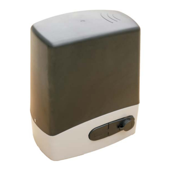
Motoriduttore elettromeccanico per cancello scorrevole
Electromechanical gear motor for sliding gate
Motoréducteur électromécanique pour portail coulissant
Istruzioni e avvertenze per l'installazione, l'uso e la manutenzione
Instructions and warnings for installation, use and maintenance
Instructions et avertissements pour l'installation, l'usage et l'entretien
Ver. 1.1 - 23/01/2014
Advertisement
Table of Contents

Subscribe to Our Youtube Channel
Related Manuals for Leb Electronics BOOST


Summary of Contents for Leb Electronics BOOST
- Page 1 BOOST Motoriduttore elettromeccanico per cancello scorrevole Electromechanical gear motor for sliding gate Motoréducteur électromécanique pour portail coulissant Istruzioni e avvertenze per l’installazione, l’uso e la manutenzione Instructions and warnings for installation, use and maintenance Instructions et avertissements pour l'installation, l'usage et l'entretien...
- Page 2 - Il dispositivo è stato realizzato appositamente per automatizzare cancelli scorrevoli. Ogni altro uso è da considerarsi improprio e quindi vietato. - Utilizzare sempre componenti originali. La ditta Leb electronics non si assume alcuna responsabilità per danni dovuti all’utilizzo di componenti non originali.
-
Page 3: Caratteristiche Tecniche
ITALIANO CARATTERISTICHE TECNICHE DATI TECNICI BOOST 5 BOOST 10 BOOST 24 Tensione di alimentazione 230Vac - 50 Hz 230Vac - 50 Hz 24Vdc Assorbimento di corrente 1.2 A Potenza motore 90 W 120 W 60 W Condensatore 6 μF 10 μF Velocità... -
Page 4: Verifiche Preliminari
ITALIANO INSTALLAZIONE Verifiche preliminari Prima di procedere con l’installazione di BOOST verificare i seguenti punti: - Assicurarsi che il dispositivo lavori entro i suoi limiti d’impiego ricavabili dalla tabella delle caratteristiche tecniche. - Verificare che la struttura del cancello sia solida e che il medesimo scorra senza attriti o altri impedimenti. - Page 5 ITALIANO Fig.3 Fig.4 - Prima di fissare la piastra di fondazione, predisporre una o più guaine per il passaggio dei cavi elettrici. Il passaggio dei cavi deve coincidere con l’apposito foro ricavato nella piastra. - Fissare la piastra di ancoraggio alla base di calcestruzzo mediante viti e tasselli idonei.
- Page 6 ITALIANO ITALIANO Installazione del motoriduttore - Svitare le due viti laterali e togliere il coperchio (Fig. 5). - Appoggiare il dispositivo sulla piastra di fondazione facendo attenzione che i fori di ancoraggio coincidano con le asole (Fig. 6). - Regolare orizzontalmente la distanza del dispositivo dal cancello. Successivamente serrare completamente le due viti di ancoraggio.
- Page 7 ITALIANO Istruzioni per l’utilizzo dei Finecorsa magnetici Fig. 8 A seconda della polarità, indicata dalle scritte “N” o “S”, il magnete attiva il finecorsa di apertura o di chiusura. Fig. 9 Per determinare in che direzione fissare il magnete, scorrere lo stesso in prossimità del sensore (3-4cm sopra l'ingranaggio).
-
Page 8: Collegamenti Elettrici
- La casa costruttrice raccomanda vivamente l’utilizzo di centrali di comando prodotte dalla stessa. - Tutte le operazioni di collegamento devono essere effettuate in assenza di energia elettrica. Cavo di alimentazione BOOST 5 – 230Vac BOOST 24 – 24Vdc BOOST 10 – 230Vac Colore Cavo 2 x 1,5 mm... -
Page 9: Manutenzione
ITALIANO Collegamento condensatore - Nei motoriduttori BOOST 5 e BOOST 10 collegare il condensatore tra il filo nero (Apre) ed il filo marrone (Chiude) del motore elettrico. Cavo Finecorsa Il dispositivo è dotato di due Finecorsa magnetici. Dal blocchetto Finecorsa escono quattro fili. Nella tabella seguente sono riportati i dati relativi al cavo Finecorsa, necessari per l’allacciamento alla... - Page 10 ENGLISH Warnings - This manual is intended only for qualified technical staff and not for end users. It is responsibility of installer to inform end user on the use of the operator and on dangers that could derive from it, as well as on the need of a periodical maintenance.
-
Page 11: Technical Features
ENGLISH TECHNICAL FEATURES TECHNICAL DATA BOOST 5 BOOST 10 BOOST 24 Power supply voltage 230 Vac - 50 Hz 230 Vac - 50 Hz 24 Vdc Current absorption 1.2 A Engine power 90 W 120 W 60 W Capacitor 6 μF 10 μF... -
Page 12: Preliminary Checks
ENGLISH SET UP Preliminary checks Before proceeding with the set up of BOOST check the following points: - Make sure the operator works within its limits obtainable from the table of technical features. - Check the gate frame is s... - Page 13 ENGLISH Fig.3 Fig.4 - Before fixing the base plate, predispose one or more sheaths for the electric wires. Terminals of sheaths must reach the hole predisposed in the base plate. - Fix the base plate on the concrete base through suitable screws and plugs.
- Page 14 ITALIANO ENGLISH Set up of the operator - Unscrew the two side screws and remove the cover (Fig. 5). - Place the operator on the base plate making sure that the anchoring holes match with the slots (Fig. 6). - Adjust the horizontal distance of the operator from the gate. Then tighten firmly the two anchoring screws.
- Page 15 ENGLISH Instructions for magnet limit switches installation Fig. 8 Depending on the polarity indicated by the letters "N" or "S", the magnet activates the opening or closing limit switch. Fig. 9 To determine in which direction attach the magnet, scroll the magnet close to the sensor (3- 4 cm above the gear).
-
Page 16: Electric Connections
Attention - The manufacturer strongly recommends the use of his control units. - All connection operations must be performed without electric mains. Power supply cable BOOST 5 - 230Vac BOOST 24 - 24Vdc BOOST 10 - 230Vac Colour Cable 2 x 1,5 mm... -
Page 17: Maintenance
ENGLISH Capacitor connection - In the motors BOOST5 and BOOST10 connect the capacitor between the black wire (Open) and the brown wire (Close) of the electric engine. Cable of limit switches operator is equipped with two magnets (cams) that travel limits of the operator. - Page 18 FRANCAIS Notice - Ce manuel est n'est destiné qu'à du personnel technique qualifié et non à l'usager final. C'est une tâche de l'installateur que d'informer ensuite l'usager sur l'utilisation de l'automatisme et les possibles dangers qui peuvent en découler aussi bien que sur la nécessité d'un entretien périodique.
-
Page 19: Caracteristiques Techniques
FRANCAIS CARACTERISTIQUES TECHNIQUES DONNEES TECHNIQUES BOOST 5 BOOST 10 BOOST 24 Tension d’alimentation 230 Vac - 50 Hz 230 Vac - 50 Hz 24 Vdc Absorption de courant 1.2 A Puissance moteur 90 W 120 W 60 W Condensateur 6 μF 10 μF... -
Page 20: Vérifications Préliminaires
FRANCAIS INSTALLATION Vérifications préliminaires Avant de procéder avec l'installation de BOOST vérifier les points suivants: - S'assurer que le dispositif travaille entre ses limites d'emploi qui peuvent être tirées de la table des caractéristiques techniques. - S'assurer que la structure de la grille est solide et que celle-ci glisse sans de frottements ou autres empêchements. - Page 21 FRANCAIS Fig.3 Fig.4 - Avant de fixer la plaque de fondation, prédisposer une ou plus gaine pour le passage des câbles électriques. Le passage des câbles doit coïncider avec le trou expressément obtenu dans la plaque. - Fixer la plaque d'ancrage à la base en béton par des vis et des chevilles convenables.
- Page 22 ITALIANO FRANCAIS Installation du moto-réducteur - Dévisser les deux vis latérales et retirer le couvercle (Fig. 5). - Appuyer le dispositif sur la plaque de fondation en faisant attention que les trous d'ancrage coïncident avec les boutonnières (Fig. 6). - Régler horizontalement la distance du dispositif de la grille. Ensuite serrer complètement les deux vis d'ancrage.
- Page 23 FRANCAIS Instructions pour l'utilisation des Fin de course magnétiques Fig. 8 Selon la polarité indiquée par les lettres « N » ou « S », l'aimant active la fin de course de ouverture ou fermeture. Fig. 9 Afin de déterminer comment appliquer l'aimant (direction), mouvoir en horizontal l'aimant près du capteur fin de course...
-
Page 24: Connexions Electriques
- Le fabricant recommande fortement l'utilisation des ses platines électriques. - Toutes les opérations de connexion doivent être effectuées sans énergie électrique. Câble d'alimentation BOOST 5 - 230Vac BOOST 24 - 24Vdc BOOST 10 - 230Vac Couleur Câble 2 x 1,5 mm Couleur Câble 4 x 0,5 mm... -
Page 25: Entretien
FRANCAIS Branchement condensateur - Dans les moto-réducteurs BOOST 5 et BOOST 10 brancher le condensateur entre le fil noir (Ouvre) et le fil marron (Ferme) du moteur électrique. Câble Fin de Course Le dispositif est équipé avec deux Fin de course magnétiques. Du blochet Fin de Course sortent quatre fils.
Need help?
Do you have a question about the BOOST and is the answer not in the manual?
Questions and answers