Table of Contents
Advertisement
Quick Links
Advertisement
Table of Contents

Related Manuals for IMPETUS IR 6500am


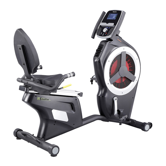
Summary of Contents for IMPETUS IR 6500am
-
Page 2: Table Of Contents
INTRODUCTION / IMPORTANT INFORMATION PACKING LIST ASSEMBLY INSTRUCTIONS HOW TO MOVE THE TRAINER TELEMETRIC HEART RATE CHEST STRAP WARM UP / COOL DOWN CLEANING & MAINTENANCE RECYCLING INFORMATION ADDITIONAL INFORMATION... -
Page 3: Introduction / Important Information
INTRODUCTION / IMPORTANT INFORMATION A. Introduction This user manual contains assembly, operation, maintenance and safety information. Please read and retain this manual for future reference. B. Safety guidelines a. Read the user manual and all accompanying literature. Follow it carefully before using your machine. - Page 4 IMPORTANT: THE MAXIMUM RECOMMENDED WEIGHT CAPACITY FOR YOUR EQUIPMENT IS KGS. WARNING: Before commencing with any exercise program, please consult your family physician. If at any time during exercise you feel faint, dizzy or experience pain, stop and consult your family physician. The safety level of the equipment can be maintained only if it is examined regularly for damaged and wear.
-
Page 5: Packing List
PACKING LIST :... - Page 6 screw M6*12mm 1PCS screw M8*20mm 2PCS screw M8*16mm 8PCS washer M8*Ø19*1.5T 2PCS screw M8*55mm 2PCS Screw Driver...
-
Page 7: Assembly Instructions
ASSEMBLY INSTRUCTIONS : STEP 1 1. Remove two BOLTS (B4), two WASHERS (A21), two NUTS (A22) and a PACKING TUBE from the MAIN FRAME (A1). 2. Attach the FRONT STABILIZER (B1) to the MAIN FRAME (A1) using two BOLTS (B4), two WASHERS (A21) and two NUTS (A22) removed earlier. STEP 2 1. - Page 8 STEP 3 Attach the SEAT RAIL ADJUSTMENT BAR (F34) to the SEAT FRAME (F1) using SCREW (F33). STEP 4 Attach the SEAT (F35) to the SEAT FRAME (F1) using four SCREWS (A12).
- Page 9 STEP 5 Attach the BACK CUSHION (F36) to the BACKREST FRAME (F2) using four SCREWS (A12) . STEP 6 1. Connect the WIRE (E8) of REAR HANDLEBAR (E1) to the WIRE (F42) of SEAT FRAME (F1). 2. Attach the REAR HANDLEBAR (E1) to the SEAT FRAME (F1) using two SCREWS (E6) and two WASHERS (E7).
- Page 10 STEP 8 1. Insert WIRES (A10 & A15) through the FRONT HANDLEBAR (G1). 2. Attach the FRONT HANDLEBAR (G1) to the MAIN FRAME (A1) using two SCREWS (G3). 3. Remove four SCREWS (H2) from the back of the CONSOLE (H1). 4.
- Page 11 STET 9 1. Attach the RIGHT PEDAL (D3R) to the CRANK (D4R) using the wrench provided and rotate in the direction as the picture shown. 2. Repeat the above step for the other side.
-
Page 12: How To Move The Trainer
HOW TO MOVE THE TRAINER HANDLE TRANSPORT WHEEL 1. Hold the handle and lift the trainer up, so the transport wheels touch the floor. 2. Move the trainer to your designated position while lifting the trainer. 3. Carefully let down the trainer. Make sure the trainer is placed on the flat floor, and rotate the leveling foot clockwise or counter-clock wise, so the leveling foot touches the floor. - Page 13 SEAT ADJUSTMENT SEAT LATERAL POSITION ADJUSTMENT To adjust the lateral position of the seat, pull up the seat handle. Then, move the seat forward or backward to the comfortable position, and firmly tighten the seat handle. SEAT ANGLE ADJUSTMENT Adjust the seat angle while pushing down the left seat handle. Let go of the seat handle when the adjustment is complete.
-
Page 15: Warm Up / Cool Down
WARM UP / COOL DOWN Suggested Stretches The following stretches provide a good warm-up and cool-down. Move slowly as you stretch. Ham String Stretch Sit with one leg extended. Bring the sole of the opposite foot toward you, resting it against the extended leg's inner thigh. -
Page 16: Cleaning & Maintenance
CLEANING & MAINTENANCE Inspect and tighten all parts of the exercise trainer regularly. Replace any worn parts immediately. To clean the exercise trainer, use damp cloth and a small amount of mild soap. IMPORTANT: To avoid damage to the console, keep liquids away from the console and keep the console out of direct sunlight.
Need help?
Do you have a question about the IR 6500am and is the answer not in the manual?
Questions and answers