Table of Contents
Advertisement
Quick Links
TECHNICAL MANUAL
KFC-S-2T-250D
KFC-S-2T-400D
KFC-S-2T-500D
Kaysun reserves the right to discontinue or change specification or designs at any time without notices and without
incurring obligations.
Ceiling&Floor Series
KFC-S-2T-900D
KFC-SE-2T-250D
KFC-SE-2T-400D
DC Fan Coil Unit
KFC-SE-2T-500D
KFC-SE-2T-900D
Advertisement
Table of Contents

Subscribe to Our Youtube Channel
Related Manuals for Frigicoll Kaysun KFC-S-2T-250D


Summary of Contents for Frigicoll Kaysun KFC-S-2T-250D
- Page 1 TECHNICAL MANUAL DC Fan Coil Unit Ceiling&Floor Series KFC-S-2T-250D KFC-S-2T-900D KFC-SE-2T-500D KFC-S-2T-400D KFC-SE-2T-250D KFC-SE-2T-900D KFC-S-2T-500D KFC-SE-2T-400D Kaysun reserves the right to discontinue or change specification or designs at any time without notices and without incurring obligations.
-
Page 2: Table Of Contents
Ceiling & Floor DC Fan Coil Unit 1.Features ....................2 2.External Appearance ................2 3.Products Lineup ................. 3 4.Nomenclature..................3 5.Specifications ..................4 6.Capacity Table ..................4 7.Dimensions ..................17 8.Sound Levels ..................20 9.Service Spaces ................. 10 10.Wiring Diagrams ................21 11.Installation .................. -
Page 3: Features
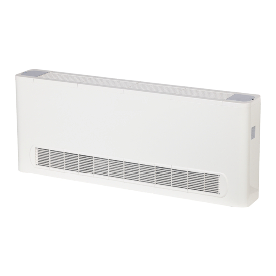
DC Fan Coil Unit 1. Features Flexible for installation, designed for horizontal/vertical, concealed/cabinet application Ceiling Installation Floor Installation Concealed Installation High efficiency and low operating sound level Due to the DC fan motor, the unit operates in lower power consumption and lower operating sound level. Meet CE certification requirements The unit can meet the latest CE certification requirements for using DC fan motor. -
Page 4: Products Lineup
3. Products Lineup Air volume Model External static pressure Power supply (CFM) KFC-SE-2T-250D/KFC-S-2T-250D KFC-SE-2T-400D/KFC-S-2T-400D KFC-SE-2T-500D/KFC-S-2T-500D KFC-SE-2T-900D/KFC-S-2T-900D 4. Nomenclature K FC S – 250 D D: Power type Nominal air volume (CFM) Type code S: Exposed SE: Concealed Fan Coil Unit Kaysun... -
Page 5: Specifications
DC Fan Coil Unit 5. Specifications KFC-SE-2T-250D Model KFC-S-2T-250D Power supply V/Ph/Hz 220-240/1/50 369/272/196 Air flow (H/M/L) 217/160/115 External static pressure H3 models: 12; H4/H5 models: 0 Capacity (H/M/L) 2.07/1.52/1.07 Water flow rate(H/M/L) 0.36/0.27/0.20 Cooling Water pressure drop(H/M/L) 11.13/6.7/3.8 Power input(H/M/L) 17/10/7 Capacity (H/M/L) 2.39/1.76/1.3... - Page 6 KFC-SE-2T-400D KFC-SE-2T-500D Model KFC-S-2T-400D KFC-S-2T-500D Power supply V/Ph/Hz 220-240/1/50 604/448/343 748/555/398 Air flow (H/M/L) 355/263/201 440/326/234 External static pressure H3 models: 12; H4/H5 models: 0 Capacity (H/M/L) 3.25/2.63/2.12 4.82/3.73/2.8 Water flow rate(H/M/L) 0.59/0.49/0.38 0.85/0.65/0.51 Cooling Water pressure drop(H/M/L) 23.2/16.38/11.14 27.32/17.1/10.74 Power input(H/M/L) 30/16/10 31/16/10...
- Page 7 DC Fan Coil Unit KFC-SE-2T-900D Model KFC-S-2T-900D Power supply V/Ph/Hz 220-240/1/50 1509/1054/806 Air flow (H/M/L) 887/620/474 External static pressure H3 models: 12; H4/H5 models: 0 Capacity (H/M/L) 7.17/5.67/4.72 Water flow rate(H/M/L) 1.29/0.99/0.84 Cooling Water pressure drop(H/M/L) 30.94/18.96/14.04 Power input(H/M/L) 103/38/21 Capacity (H/M/L) 8.45/6.32/5.05 Water flow rate(H/M/L)
-
Page 8: Capacity Table
Capacity Table Cooling Capacity Table KFC-SE-2T-250D Indoor Indoor temperature (D.B.) EWT ΔT temp (W.B.) ℃ ℃ ℃ 1.97 0.56 19.87 1.94 1.71 0.56 19.44 1.95 1.93 0.56 19.58 2.14 2.14 0.61 22.99 2.34 2.34 0.67 26.87 2.56 1.47 0.73 31.2 2.54 1.69 0.73 30.86 2.48 1.88 0.71 29.57 2.43 2.08 0.69 28.51 2.45... - Page 9 DC Fan Coil Unit (Continued) KFC-SE-2T-250D Indoor Indoor temperature (D.B.) EWT ΔT temp (W.B.) ℃ ℃ ℃ 0.88 0.88 0.25 1.09 1.09 0.31 6.92 0.37 9.34 1.51 1.51 0.43 12.04 1.72 1.72 0.49 1.11 0.86 0.32 7.12 1.16 0.33 7.72 0.37 9.38 1.51...
- Page 10 KFC-SE-2T-400D Indoor Indoor temperature (D.B.) ΔT temp (W.B.) WF WPD ℃ ℃ ℃ 2.64 2.06 0.76 31.79 2.63 2.37 0.75 31.52 2.7 0.77 32.9 2.97 2.97 0.85 38.9 3.25 3.25 0.93 45.63 3.44 0.99 50.24 3.42 2.31 0.98 49.82 3.4 2.62 0.98 49.3...
- Page 11 DC Fan Coil Unit (Continued) KFC-SE-2T-400D Indoor Indoor temperature (D.B.) EWT ΔT temp (W.B.) WF WPD WF WPD WF WPD ℃ ℃ ℃ 1.21 1.21 0.35 7.94 1.51 1.51 0.43 11.54 1.8 0.52 15.66 2.09 2.09 20.28 2.38 2.38 0.68 25.38 1.47 1.18 0.42 11.01 1.57...
- Page 12 KFC-SE-2T-500D Indoor temperature (D.B.) Indoor EWT ΔT temp (W.B.) WF WPD WF WPD WF WPD ℃ ℃ ℃ 3.98 3.02 1.14 41.79 3.9 3.43 1.12 40.39 3.94 3.89 1.13 41.06 4.31 4.31 1.24 48.08 4.71 4.71 1.35 56.23 5.16 2.97 1.48 65.81 5.12 1.47 64.9 4.96 3.77 1.42 61.47 4.91...
- Page 13 DC Fan Coil Unit (Continued) KFC-SE-2T-500D Indoor Indoor temperature (D.B.) EWT ΔT temp (W.B.) ℃ ℃ ℃ 1.78 1.78 0.51 9.99 0.63 14.42 2.62 2.62 0.75 19.47 3.04 3.04 0.87 25.11 3.45 3.45 0.99 31.3 2.26 1.73 0.65 15.09 2.36 2.22 0.68 16.2 2.63 2.63 0.75 19.55 3.04...
- Page 14 KFC-SE-2T-900D Indoor Indoor temperature (D.B.) EWT ΔT temp (W.B.) WF WPD WF WPD WF WPD WF WPD ℃ ℃ ℃ 5.61 4.45 1.61 31.1 5.16 30.99 5.85 5.85 1.68 33.48 6.46 6.46 1.85 39.83 7.09 7.09 2.03 46.83 7.32 49.44 7.28 2.09 7.25 5.69...
- Page 15 DC Fan Coil Unit (Continued) KFC-SE-2T-900D Indoor Indoor temperature (D.B.) EWT ΔT temp (W.B.) WF WPD WF WPD WF WPD WF WPD ℃ ℃ ℃ 2.62 2.62 0.75 8.04 3.27 3.27 0.94 11.73 3.91 3.91 1.12 15.96 4.55 4.55 1.31 20.73 5.18 5.18 1.49 3.09...
- Page 16 Heating Capacity Table KFC-SE-2T-250D Indoor temperature (D.B.) ΔT ℃ ℃ 2.39 0.41 2.16 0.37 7.94 1.92 0.33 6.51 1.69 0.29 5.22 2.32 0.34 6.61 2.09 1.85 0.27 4.49 1.62 0.23 3.56 2.18 0.24 3.65 1.95 0.21 1.71 0.19 2.41 1.48 0.16 1.88 2.04...
- Page 17 DC Fan Coil Unit KFC-SE-2T-500D Indoor temperature (D.B.) ΔT ℃ ℃ 4.78 0.83 19.6 4.31 0.75 16.36 3.84 0.66 13.41 3.37 0.58 10.73 4.64 0.67 13.63 4.17 11.33 0.53 9.23 3.24 0.47 7.32 4.37 0.47 7.51 0.42 6.17 3.43 0.37 4.95 2.96 0.32...
-
Page 18: Dimensions
6. Dimensions Cased type Dimensions (unit: mm) Size 250D 400D 500D 900D 1000 1200 1500 1284 1200 1226... - Page 19 DC Fan Coil Unit Uncased type Dimensions (unit: mm) Size 250D 400D 500D 900D 1250 1226 1200 1232...
-
Page 20: Sound Levels
7. Sound Levels Model 250D 400D SE (H/M/L) 39/31/22 44/37/31 S (H/M/L) 39/31/22 44/37/31 Model 500D 900D SE (H/M/L) 42/35/27 51/42/35 S (H/M/L) 42/35/27 51/42/35... -
Page 21: Service Spaces
DC Fan Coil Unit 8. Service Spaces Cased type ≥a ≥a ≥b a (mm) ≥a ≥a b (mm) Uncased type ≥ b a (mm) ≥a ≥a b (mm) -
Page 22: Wiring Diagrams
9. Wiring Diagrams... -
Page 23: Installation
DC Fan Coil Unit 10. Installation 10.1 Transport and handling Caution: Do not open or tamper with the packaging before installation. The units should only be moved and lifted by specialized personnel trained in these operations. Check on arrival that the unit has not been damaged during transport and that it is complete with all its parts. To remove the packaging, please follow below instructions: Check for visible damage. -
Page 24: Units Installation
Uncased type ≥ b a (mm) ≥a ≥a b (mm) 10.4 Units installation Caution: Installation must only be carried out by qualified technicians, trained to work with air-conditioning and refrigeration systems. Incorrect installation could lead to unit malfunctioning and a consequent deterioration in performance. For installation, follow the instructions set out below: Remove the external casing, unscrewing the screws which secure it to the structure, as following indicated. - Page 25 DC Fan Coil Unit Parts instruction: 1. Pipe connections; 2. Fixing slots; 3. Defrosting tray; 4. Condensate discharge; 5. Air filter; 6. Fans; 7. Heat exchanger; Mark out the fixing points on the wall or ceiling either by marking through the drillings in the unit or by referring to the measurements given in “7 DIMENSIONS”.
-
Page 26: Electrical Connections
The condensation drainage system must be set up with an adequate fall to ensure that the water escapes properly. Following are directions for setting up a proper condensation drainage system. connect to the unit condensate discharge or defrosting tray. Creation of the trap The condensation drainage system must be fitted with a suitable trap to prevent seepage of odors. - Page 27 DC Fan Coil Unit effect in the country where the unit is installed. The company shall not be held liable for damage to persons or property caused by incorrect electrical connection. The power cord type designation is H05RN-R or above/H07RN-F. This appliance can be operated by children aged from 8 years and above and persons with reduced physical sensory or mental capabilities or lack of experience and knowledge, if they have been given supervision or instruction concerning use of the appliance in a safe way and understand the hazards involved.
-
Page 28: Maintenance
Preliminary checks before startup Before starting up the unit, make sure that: The unit is positioned correctly; The flow and return pipes of the water system are correctly connected; The pipes are clean and free of air; The unit falls correctly towards the drainage outlet and the trap; The heat-exchangers are clean;... - Page 29 DC Fan Coil Unit Loosen the release screw on the inlet manifold and release the air. Repeat the operation several times until no more air comes out of the system. At the end of the season To avoid the risk of rupture due to freezing, it is advisable to drain the water from the system at the end of every season.
- Page 31 DC Fan Coil Unit...
Need help?
Do you have a question about the Kaysun KFC-S-2T-250D and is the answer not in the manual?
Questions and answers