Garmin 400W Series Manual
Bell 206b
Hide thumbs
Also See for 400W Series:
- Pilot's manual & reference (78 pages) ,
- Instructions manual (26 pages) ,
- Pilot's manual addendum (24 pages)
Table of Contents
Advertisement
Quick Links
Instructions for Continued Airworthiness
Reg. No.____________
Rev.
Date
1
7/16/10
2
8/11/10
400W Series
Bell 206B
Dwg. Number:
190-01226-04 Rev. 2
Garmin International, Inc.
1200 E. 151st Street
Olathe, Kansas 66062 USA
Record of Revision
Initial Release
Updated ref. doc. revisions in section 2.1, revised part number and weight
of item 2 in table 2.2.1.
S/N_______________
Description of Change
Advertisement
Table of Contents

Related Manuals for Garmin 400W Series


Summary of Contents for Garmin 400W Series
- Page 1 400W Series Instructions for Continued Airworthiness Bell 206B Reg. No.____________ S/N_______________ Dwg. Number: 190-01226-04 Rev. 2 Garmin International, Inc. 1200 E. 151st Street Olathe, Kansas 66062 USA Record of Revision Rev. Date Description of Change 7/16/10 Initial Release 8/11/10 Updated ref. doc. revisions in section 2.1, revised part number and weight...
-
Page 2: Table Of Contents
2.14 Overhaul Period....................21 2.15 ICA Revision and Distribution ................21 2.16 Assistance......................22 2.17 Implementation and Record Keeping ..............22 3. AIRWORTHINESS LIMITATIONS ..................22 400W Series 190-01226-04 Rev. 2 Instructions for Continued Airworthiness Bell 206B Page 2 of 22... -
Page 3: Introduction
1.4 Permission to Use Certain Documents Permission is granted to any corporation or person applying for approval of a Garmin Model 400W series to use and reference appropriate STC documents to accomplish the Instructions for Continued Airworthiness and show compliance with STC engineering data. -
Page 4: Instructions For Continued Airworthiness
2.1 Introduction Content, Scope, Purpose and Arrangement: This document identifies the Instructions for Continued Airworthiness for the modification of the rotorcraft by installation of the Garmin 400W Series GPS/WAAS Nav/Com units. Applicability: Applies to Bell models 206B rotorcraft altered by installation of the Garmin 400W Series GPS/WAAS Nav/Com units. -
Page 5: Description Of Alteration
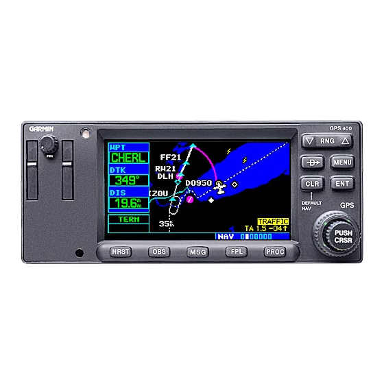
This STC upgrades existing avionics for the Bell 206B rotorcraft as summarized below. The Garmin Model 400W Series GPS/WAAS Nav/Com unit is a 6 ¼ inch wide unit mounted in the center pedestal of the Bell 206B. The 400W Series units combine a large number of easily accessible controls to use the color multi-function display, Nav and Com transceiver, GPS/WAAS navigator in a single unit. - Page 6 0.50 Only) [1] A rotorcraft weight and balance is required after installation of the 400W Series Unit. Refer to the 400W Rotorcraft STC Installation Manual listed in paragraph 2.1 of this document, for additional information, including overall size and center of gravity location of all LRUs.
-
Page 7: Control, Operating Information
400W Rotorcraft STC Installation Manual. 2.4 Servicing Information None. In the event of system failure, troubleshoot the 400W Series unit in accordance with Section 2.6. 2.5 Periodic Maintenance Instructions The 400W Series units are designed to detect internal failure. A thorough self-test is executed automatically upon application of power to the units, and built-in test is continuously executed. -
Page 8: Troubleshooting Information
The display backlight lamp is rated by the manufacturer as having a usable life of 20,000 hours. This life may be more or less than the rated time depending on the operating conditions of the 400W Series unit. Over time, the backlight lamp may dim and the display may not perform as well in direct sunlight conditions. - Page 9 (ARINC 429 • Wiring connections are • Check wiring. heading input used) incorrect. • 400W Series unit does not have • Autopilot is not Acquire GPS position and enter a getting GPSS/Roll a position or flight plan entered. flight plan.
- Page 10 • Device not compatible, or • Verify 400W Series unit RX is improper connection. connected to remote device TX and 400W Series unit TX is connected to remote device Rx. • Multiple TX lines connected • Verify that there is only one TX together.
- Page 11 Reconfigure EFS 40/50 for CDI scaling on EFS configuration is not set to KLN 90-GPS” on FMS #1/#2 inputs 40/50 is not correct. “KLN 90-GPS”. as appropriate. 400W Series 190-01226-04 Rev. 2 Instructions for Continued Airworthiness Bell 206B Page 11 of 22...
- Page 12 2.6.1 400W Series Alerts The 400W Series will display a number of alerts. These are listed in the following table. Table 3. 400W Series Alert Troubleshooting Guide Alert Text Possible Cause Solution • The 400W Series unit has • The data is not usable, try...
- Page 13 Alert Text Possible Cause Solution • Internal system-to-system • Contact Garmin technical COM is not responding communication between the support. If the COM board is 420W and 430W only) main processor and the COM still working, it will automatically transceiver has failed.
- Page 14 Display backlight failure detected a failure in the display support. backlighting. • The 400W Series unit is in • Check that the DEMO MODE Do not use for navigation Demo Mode and must not be SELECT pin, P5001 Pin 75, is used for actual navigation.
- Page 15 GPS receiver has failed. Operational status of the GPS receiver is unknown. • The 400W Series unit has • Contact Garmin technical GPS needs service detected a failure in its GPS support. receiver. • A valid value of magnetic •...
- Page 16 400W Series unit does not compute a position.” • The 400W Series unit has • The data is not usable. Try Obstacle database integrity detected a problem with a reloading the information onto...
- Page 17 • Reload the TERRAIN database. • Contact Garmin technical support. • The 400W Series unit cannot • Check for proper configuration Traffic device has failed communicate with the traffic system and/or the traffic • Check for correct wiring system is reporting a system •...
- Page 18 • Check for proper configuration WX-500 heading has failed invalid heading data. of WX-500 • The failure may be within the WX-500 or other connected equipment. 400W Series 190-01226-04 Rev. 2 Instructions for Continued Airworthiness Bell 206B Page 18 of 22...
-
Page 19: Removal And Installation Information
New, Repaired or Exchange 400W Series is Installed If the 400W Series unit is removed for repair and reinstalled, or if the 400W unit is removed and replaced with a different 400W Series unit, then verify the correct software versions are on the 400W Series unit as specified in the Equipment List 400W/500W Series Installation Bell 206B STC listed in paragraph 2.1... -
Page 20: Diagrams
Installation drawing Bell 206B, listed in Section 2.1 of this document Point to point wiring diagrams are in the Appendix of the 400W Rotorcraft STC Installation Manual. Refer to the GNS 400W Series Post- Installation Checkout Log retained in the rotorcraft permanent records for a list of the interfaced equipment and port configurations. -
Page 21: Special Inspection Requirements
The system does not require overhaul at a specific time period. Power on self-test and continuous BIT will monitor the health of the 400W Series unit. If the unit indicates an internal failure, the unit may be removed and replaced. See troubleshooting section 2.6 contained in this document. -
Page 22: Assistance
The latest revision of this document will be available through any Garmin dealer or from Garmin customer assistance. A Garmin Service Bulletin, describing ICA revision, will be sent to dealers if revision is determined to be significant. 2.16 Assistance FAA Flight Standards Inspectors or the certificate holder’s PMI have the required resources to respond to questions regarding this ICA.
Need help?
Do you have a question about the 400W Series and is the answer not in the manual?
Questions and answers