
Related Manuals for UTC Fire and Security AirSense Stratos EX


Summary of Contents for UTC Fire and Security AirSense Stratos EX
- Page 1 Stratos EX Hazardous Area Aspirating Smoke Detection System Installation Manual P/N 9-14519 • R02 • ISS 16APR12...
- Page 2 © 2012 Kidde Products Ltd. All rights reserved. Copyright Kidde Products Limited Manufacturer Unit 2 Blair Way Dawdon City: Seaham, County Durham SR7 7PP United Kingdom Telephone: +44 (0)191-513 6100 Fax: +44 (0)191-513 6102 Certification For contact information, see www.airsensetechnology.com. Contact information...
-
Page 3: Table Of Contents
Content Important information ii Chapter 1 Introduction 1 About this manual 2 Safety summary 2 Aspirating Smoke Detection System Limitations 4 Chapter 2 Product description 7 Introduction 8 Available software for the EX detector 9 Specifications 10 Features 11 Indicators 12 Outside the detector 13 Inside the detector 14 Detector connections 15... -
Page 4: Important Information
Important information Regulatory information The EX detector series has been certified according to: ATEX Directive 94/9/EC and the requirements laid down by the following standards: Standard Description EN 60079.0: 2009 Explosive atmospheres equipment General requirements EN 60079-1: 2007 Electrical apparatus for potentially explosive atmospheres Flameproof enclosure ‘d’... - Page 5 The foregoing limitation will apply to the maximum extent permitted by applicable law, regardless of whether Kidde Products Ltd. has been advised of the possibility of such damages and regardless of whether any remedy fails of its essential purpose. Installation in accordance with this manual, applicable codes, and the instructions of the authority having jurisdiction is mandatory.
-
Page 7: Introduction
Chapter 1 Introduction Summary This chapter provides information about this manual. Content About this manual 2 Safety summary 2 General safety notices 2 First aid 2 General precautions 3 Installation precautions 3 Aspirating Smoke Detection System Limitations 4 Stratos EX Hazardous Area Aspirating Smoke Detection System Installation Manual... -
Page 8: About This Manual
Chapter 1: Introduction About this manual This manual is to be used by qualified and factory-trained personnel, knowledgeable of all applicable standards in effect, and is intended to provide guidance to qualified technical professionals for the installation, operation, testing and maintenance of the EX Hazardous Area Aspirating Smoke Detection System, referred to in this manual as the “EX”... - Page 9 Chapter 1: Introduction General precautions The following general safety precautions are to be observed at all times: • All electrical components associated with equipment should be installed and grounded in accordance with NEC and local regulatory requirements. • Special precautionary measures are essential to prevent applying power to equipment at any time maintenance work is in progress.
-
Page 10: Aspirating Smoke Detection System Limitations
Chapter 1: Introduction Do not install electronic assemblies prior to mounting and attaching conduit for field wiring to the enclosure. Before making modifications, verify that they will not interfere with battery and printed circuit board locations. Do not overtighten screw terminals. - Page 11 Chapter 1: Introduction • Notification appliances, such as bells, may not alert people if these appliances are located on the other side of closed or partly open doors, or are located on another floor of a building. • A fire alarm system will not operate without electrical power. If AC power fails, the system will operate from standby batteries only for a specified time.
- Page 12 Chapter 1: Introduction Stratos EX Hazardous Area Aspirating Smoke Detection System Installation Manual...
-
Page 13: Product Description
Chapter 2 Product description Summary This chapter provides descriptions of the detector features, specifications, and controls and indicators. Content Introduction 8 Available software for the EX detector 9 Specifications 10 Recommended cable 11 Features 11 Indicators 12 Outside the detector 13 Inside the detector 14 Detector connections 15 Stratos EX Hazardous Area Aspirating Smoke Detection System Installation Manual... -
Page 14: Introduction
Chapter 2: Product description Introduction The EX detector is a highly sophisticated “next generation” high sensitivity aspirating smoke detection product that provides all the benefits of air sampling high sensitivity smoke detection, including very early warning. Designed for easy installation and commissioning, the EX detector incorporates a patented “artificial intelligence”... -
Page 15: Available Software For The Ex Detector
Chapter 2: Product description The EX detector is ATEX approved and is rated at EEx d IIB + H2 T3 (Tamb -20°C to +45°C) or T2 (Tamb -20°C to +60°C). The explanation of this rating is as follows: Carries a certificate in accordance with European harmonised standards Explosion-proof electrical equipment Protected by a flameproof enclosure Equipment class II (for surface industries) -
Page 16: Specifications
Chapter 2: Product description Specifications This equipment is only to be used in accordance with this specification. Caution: Failure to operate the equipment as specified may cause damage to the unit, injury, or property damage. Table 1: Specifications Specification Value Supply Voltage 21.6 - 26.4 VDC PSU Type: conforming to EN 54-4... -
Page 17: Features
Chapter 2: Product description Specification Value IP rating IP50 SELV rating (EN 60950) Class III [1]Devices, such as local sounders and beacons can demand high inrush currents, which may damage the relays. If relays are used to drive the device directly, a suitable 47 Ω current-limiting resistor should be placed in series with the load. -
Page 18: Indicators
Chapter 2: Product description Indicators Figure 1 below shows the three indicators on an EX detector. Figure 1: EX Detector indicators Inlet Illuminates to show normal operation when there are no faults. The OK lamp will flash during the 15-minute FastLearn period when the detector is first learning about its environment. -
Page 19: Outside The Detector
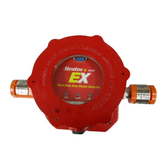
Chapter 2: Product description Outside the detector Figure 2 below shows external components on an EX detector. Removal of the detector screw down protective cover in most WARNING: applications where this product is installed will require a Hot Work permit. Figure 2: EX external components (1) Display retaining screws (2) Lid locking set screw... -
Page 20: Inside The Detector
Chapter 2: Product description Inside the detector Figure 3 below shows the main interior parts of a detector with the cover off. Figure 3: EX internal components (1) Removable terminal blocks (See “Detector connections” on page 15.) (2) Addressable Programmable Interface Card (APIC) connector (not currently supported) (3) APIC securing pillars (4) Detector address switch (See “Setting the device address”... -
Page 21: Detector Connections
Chapter 2: Product description Detector connections Figure 4 below shows the detector connections. Figure 4: Detector connections (1) Normally closed FAULT relay contact (2) Normally open FIRE relay contacts (3) Loop data to fire panel (Not currently supported) (4) RS-485 / SenseNET connections (See “Setting the device address” on page 29.) (5) Power supply (6) IDC 26 way connector for APIC card (not currently supported) (7) Fire, Fault and OK display LED connections... - Page 22 Chapter 2: Product description Stratos EX Hazardous Area Aspirating Smoke Detection System Installation Manual...
-
Page 23: Installation
Chapter 3 Installation Summary This chapter provides information necessary to install the EX detector system. Content Introduction 18 Antistatic precautions 18 Design 19 Design limitations 19 System design 19 Installation 22 Standards and requirements 23 Enclosure installation 23 Mechanical installation 25 Electrical installation 25 Interfacing 29 Setting the device address 29... -
Page 24: Introduction
Chapter 3: Installation Introduction This chapter provides information necessary to install the EX detector system. Installation consists of the following steps: 1. Determine the optimum location for the detector. 2. Mount the detector in the selected location. 3. Connect the detector to the sampling pipe network. Installation should only be done by factory-trained technicians in accordance with applicable installation requirements, standards, and codes. -
Page 25: Design
Chapter 3: Installation Design Design limitations The EX detector is intended to provide incipient fire detection. It is suitable for the range of applications typified by noncompartmentalised rooms, or items of electronic or electromechanical equipment where it is desirable to achieve incipient fire reporting. - Page 26 Chapter 3: Installation There is no substitute for carrying out smoke tests prior to installation of pipework to indicate suitable sampling point location. Remember that cool smoke from an incipient fire does not behave in the same manner as hot smoke. Figure 5: Locating the detector outside the area to be protected (1) Earth bonded metallic sampling pipe (2) Sampling hole...
- Page 27 Chapter 3: Installation Figure 6: Locating the detector within the area to be protected (1) Earth bonded metallic sampling pipe (2) Sampling hole (3) Filter (4) EX detector (5) False ceiling Figure 7: Suggested maximum sampling pipework configurations (1) End cap holes drilled to 7 mm diameter (2) Sampling holes at 5 metre intervals (3) Filter (4) EX detector...
-
Page 28: Installation
Chapter 3: Installation Installation Before installing the detector, the local standards for hazardous areas and for installation of aspirating detection systems must be consulted, as these standards differ throughout the world. Specific advice for one country may not be applicable to another. The following is a brief set of guidelines on installing detectors. -
Page 29: Standards And Requirements
Chapter 3: Installation • Pipework should be metal and bonded to earth/ground to eliminate static electricity buildup. Selection of pipe is left to the site engineers, but the internal diameter should be between 20 and 25 mm. • The exhaust air from the unit must not be impeded in any way. If the unit is mounted in a different air pressure from where the air is being sampled (for example an air duct), then a pipe must be taken from the exhaust port back to the same air pressure zone as the sampling holes. - Page 30 Chapter 3: Installation Figure 8: EX detector enclosure mounting (1) Enclosure mounting points (2) Inlet (3) Exhaust Stratos EX Hazardous Area Aspirating Smoke Detection System Installation Manual...
-
Page 31: Mechanical Installation
Chapter 3: Installation Mechanical installation The enclosure is connected to the installed sampling pipework and fixed to the wall or mounting surface using four bolts of a type appropriate to the mounting surface. It is essential that the sampling and exhaust pipes are properly screwed into the flame arrestors. - Page 32 Chapter 3: Installation Figure 10: Removing the display 4. Fit the cable glands, and then route the cables carefully up the sides of the detector assembly as shown in Figure 11 below. 5. Cut the cables to a suitable length. This should be the shortest possible length that will comfortably allow the plugs to fit their respective sockets.
- Page 33 Chapter 3: Installation Power supply connections The power supply cable should be of three-core screened type and should be led through cable gland 1 or 2, leaving about 170 mm of the cable extending from cable gland 1 or 100 mm from cable gland 2. Note the orientation of the terminal block.
- Page 34 Chapter 3: Installation Figure 13: Signal connections (1) RS-485 (SenseNET terminals) (2) APIC address terminal (not currently supported) Final installation Slot the power and signal terminal blocks into the relevant sockets on the detector PCB (they will only click fully home in the correct orientation), replace the front display using the four M3 pan-head screws provided and replace the enclosure lid.
-
Page 35: Interfacing
Chapter 3: Installation Figure 14: Final installation Interfacing Setting the device address In order to identify itself to a PC or Command Module, each detector on a SenseNET network needs to have a unique address ranging from 1 to 127. The detector address is simply set on the red DIP switch SW1 at the top right of the opened detector on the main circuit board. - Page 36 Chapter 3: Installation segment 1 through 7. (Segment 8 is not used.) An example is shown in Figure 15 below. The address equates to 00100011 in binary, or (1 x 1) + (1 x 2) + (0 x 4) + (0 x 8) + (0 x 16) + (1 x 32) + (0 x 64) = 35.
-
Page 37: Connecting An Ex Detector To A Sensenet/Rs-485 Detector Network
Chapter 3: Installation Connecting an EX detector to a SenseNET/RS-485 detector network Up to 127 detectors may be linked in a single SenseNET bus, supporting a total length of cable of up to 1.2 km. This can be extended with the use of RS-485 repeaters. -
Page 38: Configuring The Ex Detector After Installation
Chapter 3: Installation It may be easier to join the input and output wires for each bus and screen Note: connections together and to solder or crimp a single wire or connecting ferrule to each wire pair so that they are easier to fit into the screw terminals. If this is done, it is recommended that bare wire joints be insulated to prevent possible shorting of the data bus, which will cause a dropout of data on the SenseNET bus. -
Page 39: List Of Programmable Functions
Chapter 3: Installation connected via an RS-232 serial cable. Complete instructions on how to install, launch and use the the Remote Configuration Software are provided in the Remote Configuration Software User Manual under separate cover. SenseNET The SenseNET software is available for purchase. SenseNET software can configure and manage a large network of detectors with a simple, streamlined graphical user interface from a computer connected to a detector or command module via an RS-232 serial cable or RS-485 converter interface. -
Page 40: Connecting To A Pc
Chapter 3: Installation • Latching Faults • Cascading Alarms • Device Type (reference only) • Firmware Version • Run-time Hours • Watchdog Count (reference only) • Device Text • Reference Detector • Reference Enable • Reference Level • Reference Back-off •... -
Page 41: Event Log
Chapter 3: Installation Figure 18 shows the RS-232 cable connection from an EX detector to a PC. Figure 18: EX detector serial port connection for a PC (1) Serial cable (2) Serial port connection (to PC) Event log The event log is a record of detector events such as faults, alarms and function changes. - Page 42 Chapter 3: Installation To download the event log, connect a PC to the detector serial port and run the Remote Configuration Software or SenseNET programs. For details, see the Remote Configuration Software User Manual or the SenseNET Software User Manual. Stratos EX Hazardous Area Aspirating Smoke Detection System Installation Manual...
-
Page 43: Commissioning
Chapter 4 Commissioning Summary This chapter provides information about commissioning the EX detection system. Content Commissioning 38 Commissioning checklist 38 Acclimation period 40 Suction pressure verification 41 Transport time verification 42 Gross smoke testing 42 Aerosol smoke spray 42 Wire burner test 43 Stratos EX Hazardous Area Aspirating Smoke Detection System Installation Manual... -
Page 44: Commissioning
Chapter 4: Commissioning Commissioning Before commissioning the detector, the local standards of aspirating detection systems must be consulted. These standards differ throughout the world, and specific advice for the market in one country may not be applicable to another. Commissioning strategy will initially depend upon the environment in which the detector is installed. - Page 45 Chapter 4: Commissioning 5. Launch either the Remote Configuration Software or SenseNET software on the computer, enter the access code, and select the Function Settings window. 6. Verify that the time and date are correct on the Time and Date tab. 7.
-
Page 46: Acclimation Period
Chapter 4: Commissioning Table 3: Suggested settings for ClassiFire alarms Alarm Sensitivity Probability of nuisance Suggested protected area factor alarm Extremely High Once per year Semiconductor manufacturing clean room High Once per 5 years Computer room High Once per 10 years Non-smoking office High Once per 50 years... -
Page 47: Suction Pressure Verification
Chapter 4: Commissioning Suction pressure verification All sample hole suction pressures should be measured and recorded on the checklist. Measured suction pressures less than 0.5 inches of water are not acceptable. Use the following method to measure sampling point suction pressures (as illustrated in Figure 19). -
Page 48: Transport Time Verification
Chapter 4: Commissioning Transport time verification Maximum transport time verification test is the measure of the amount of time it takes for the detector to respond to smoke that enters the pipe at the sampling point furthest from the detector. The results of this test and the calculated maximum transport time from PipeCAD must be recorded on the checklist. -
Page 49: Wire Burner Test
Chapter 4: Commissioning Wire burner test The wire burner test is considered the most representative test of incipient fire hazard detection in telecommunications or computer room environments. The test is performed by applying a voltage to a piece of PVC-insulated cable. Smoke is produced from the overheated PVC insulation by evaporation and condensation of the plasticizer. - Page 50 Chapter 4: Commissioning The wire cross-section should be AWG 10 with the following diameter and Note: area: Diameter = 2.59 mm or 0.10189 in. Cross-Section Area = 5.0 mm² or 0.00775 in.² Stratos EX Hazardous Area Aspirating Smoke Detection System Installation Manual...
-
Page 51: Troubleshooting
Chapter 5 Troubleshooting Summary This chapter provides information about troubleshooting the EX detection system. Content Troubleshooting 46 Troubleshooting the EX detector 46 General troubleshooting information 47 Stratos EX Hazardous Area Aspirating Smoke Detection System Installation Manual... -
Page 52: Troubleshooting
Chapter 5: Troubleshooting Troubleshooting Troubleshooting the EX detector This chapter provides some possible solutions if a problem should occur with your EX detector. If the problem is not addressed in this chapter or, if after performing the suggested actions, the problem persists, contact Technical Support. - Page 53 Chapter 5: Troubleshooting Problem Solution or corrective action Flow fault errors These occur when the airflow rate into the detector exceeds the (“FLOW” LED programmed parameters. This usually occurs when there has been some illuminated) change in conditions. It may indicate that a sampling pipe is damaged, or that the pipe has been blocked, e.g., by nearby building operations.
- Page 54 Chapter 5: Troubleshooting • Ensure that all hazardous area safety rules are followed and correct permits to work obtained. Do not do the following: • Remove or connect boards when the detector is powered up. Connect internal 0 volt terminals to local earth. •...
-
Page 55: Maintenance
Chapter 6 Maintenance Summary This chapter provides scheduled and unscheduled maintenance procedures. Content Introduction 50 Maintenance 50 Diagnostics 53 Flame arrestors 54 Stratos EX Hazardous Area Aspirating Smoke Detection System Installation Manual... -
Page 56: Introduction
Chapter 6: Maintenance Introduction This chapter contains maintenance instructions for the EX aspirating smoke detection system. These procedures should be performed on a scheduled basis. In the event that system problems are found during routine maintenance, refer to “Troubleshooting” on page 46. Failure to properly maintain the system may affect the functioning of the system. - Page 57 Chapter 6: Maintenance All necessary safety precautions regarding the specific area should be implemented before proceeding further, if you are unsure of these please consult the site safety officer. To replace the filter, remove the front cover of the remote filter housing and pull the filters out.
- Page 58 Chapter 6: Maintenance Figure 21: Dust separator (1) From area to be protected (2) Dust separator (filter) Stratos EX Hazardous Area Aspirating Smoke Detection System Installation Manual...
- Page 59 Chapter 6: Maintenance Diagnostics The Remote Control Software includes a diagnostic function which carries out a number of checks to verify the correct functioning of the detector. A good time to run these tests is as a part of planned maintenance. To call up diagnostic mode, click View >...
- Page 60 Chapter 6: Maintenance If any problems were found during the diagnostic tests, the nature of the fault will be indicated in the “Status” column. Table 4: Diagnostics screen Function Description Scan Reads in the status of all connected detectors. Read Opens a display of the detector output and flow rate, which updates in real time.
- Page 61 Chapter 6: Maintenance 2. Unplug all cable connections. 3. Remove the inside electronics from the unit. 4. Disconnect the inlet aspiration piping from the flame arrestor. 5. Disconnect the exhaust piping from the flame arrestor. 6. Blow compressed air from inside the unit, through the flame arrestor outwards.
- Page 62 Chapter 6: Maintenance Stratos EX Hazardous Area Aspirating Smoke Detection System Installation Manual...
-
Page 63: Appendix A Mounting Template
Appendix A Mounting template Summary A mounting template is provided to assist with installation. Refer to the mounting template on the next page. Stratos EX Hazardous Area Aspirating Smoke Detection System Installation Manual... -
Page 64: Mounting Template
Appendix A: Mounting template Mounting template Stratos EX Hazardous Area Aspirating Smoke Detection System Installation Manual... -
Page 65: Index
Index A M Addressing Maintenance, 50 Address table, 30 Flame arrestors, 54 Setting the detector address, 29 Mounting template, 58 Advisory messages, iii Antistatic precautions, 18 P Aspirating Smoke Detection System Programmable functions, 33 Limitations, 4 S C Safety summary, 2 Commissioning, 38 SenseNET checklist, 38... - Page 66 Stratos EX Hazardous Area Aspirating Smoke Detection System Installation Manual...
- Page 67 Stratos EX Hazardous Area Aspirating Smoke Detection System Installation Manual...
- Page 68 Stratos EX Hazardous Area Aspirating Smoke Detection System Installation Manual...
Need help?
Do you have a question about the AirSense Stratos EX and is the answer not in the manual?
Questions and answers