Table of Contents
Advertisement
Advertisement
Table of Contents

Related Manuals for Eli Ezer ERK-9000


Summary of Contents for Eli Ezer ERK-9000
- Page 1 Operation Manual AUTO REF / KERATOMETER ERK-9000 Revison1.00 2015.03.03...
-
Page 3: Table Of Contents
Table of Contents 1. IMPORTANT NOTICE ........................... 1 1.1 Intended Use ..................................1 1.2 Classifications ..................................1 1.3 Caution ...................................... 2 2. SAFETY ................................3 2.1 SAFETY INFORMATION ..............................3 2.2 Symbol Information ................................4 2.3 Shape Of Plug ..................................5 2.4 General Safety Information .............................. - Page 4 8.1 [INFOR ] Touch Button .............................. 20 8.2 [EXIT ] Touch Button ..............................21 8.3 [REF]/[KER]/[RK]/[CLBC]/[SIZE]/[ILLUM] Touch Button ..................21 8.4 [DISPLAY] Touch Button ..............................21 8.5 [SETUP] Touch Button ............................... 21 8.6 [SLEEP] Touch Button ................................ 21 8.7 [RESET] Touch Button ............................... 21 9.
- Page 5 9.3.7 Print ....................................27 9.4 Practice through the Model Eye..........................28 9.4.1 Power ON ..................................28 9.4.2 Installation ..................................28 9.4.3 Release unlock Stage ............................... 28 9.4.4 Select RK mode or REF mode..........................28 9.4.5 Model eye position and focusing........................28 9.4.6 Measurement ................................
- Page 6 9.7.6 Comparison of images through image list ....................35 9.7.7 The observing original image through Image view .................. 36 9.7.8 Return to the measurement mode........................36 10. DISPLAY Mode ............................37 10.1 Mode Selection ................................. 37 10.2 VD, CYL, STEP changes ..............................37 10.3 Print the measurement results ...........................
- Page 7 11.4.2 KEY SOUND ................................42 11.4.3 LCD BRIGHT ................................42 11.4.4 SCREEN OFF ................................42 11.4.5 VIDEO OUT ................................. 42 11.5 DATE&TIME PAGE ................................43 11.6 MESSAGE PAGE ................................. 44 11.7 CODE ...................................... 44 12. Self Inspection and Maintenance ......................45 12.1 Before Calling a Service Person ..........................
-
Page 9: Important Notice
The ERK-9000 is classified as IPX0 [Degree of protection against flammability] The ERK-9000 is classified as a device not suitable to be used in a potentially flammable environment. Do not use near flammable materials [Method(s) of sterilization or disinfection recommended by the manufacturer]... -
Page 10: Caution
No use of the information contained herein. ERK-9000 reserves the right to make changes in its products or product specifications at any time and without prior notice, and is not required to update this documentation to reflect such changes. -
Page 11: Safety
2. SAFETY 2.1 SAFETY INFORMATION Accessory equipment connected to the analog and digital interfaces must be certificated according to the respective IEC/EN standards (e.g. IEC/EN 60950 for data processing equipment and IEC/EN 60601-1 for medical equipment). Furthermore all configurations shall comply with the system standard EN 60601-1-2:2007. Everybody who connects additional equipment to the signal input part or signal output part configures a medical system, and is therefore responsible that the system complies with the requirements of the system standard EN 60601-1-1:2001. -
Page 12: Symbol Information
2.2 Symbol Information Symbol Descriptions TYPE B EQUIPMENT Protective earth (ground) Alternating current Off (power: disconnect to the mains) On (power: connection to the mains) Do not throw away the waste to inappropriate place Crushing hazard sign Hand hazard sign Instruction for user manual Operating instructions CAUTION... -
Page 13: Shape Of Plug
Manufacture Date Only one unit in the box Temperature between - 40˚C ~ 70˚C Humidity between 10%RH ~ 95%RH Air pressure between 500hPa ~ 1060hPa 2.3 Shape Of Plug Country Voltage/frequency Shape of plug Mexico 110V/50Hz Type C&E Argentina 220V/60Hz Type A Peru 220V/60Hz... -
Page 14: General Safety Information
2.4 General Safety Information If you see any warnings or cautions printed on the warning labels, follow the safety instructions in this manual. Ignoring such cautions or warnings while handling the product may result in injury or accident. Be sure to read and fully understand the manual before using this product. -
Page 15: Cautions In Installation , Storage And Transportion
● In case you leave ERK-9000 without using for certain period, disconnect the power supply and protect the unit with dust cover. ● In case moving this ERK-9000, fix the stage by using clamping bolt and stage holding knob, always keep power off, and then lift the bottom of the unit with both hands. -
Page 16: Patient Environment
2.6 Patient environment The patient environment represents a space where there is a possibility of direct contact between the patient or the operator and third person. When another type of device is used in the patient environment, use a device that complies with IEC 60601-1. -
Page 17: Labels
2.7 Labels The following labels and indications are affixed to draw the operator’s attention AC100-240 ~... -
Page 18: Features
Wide Dioptric Measurement Range Because the ERK-9000 covers a wide measurement range, from -25D to +22D, even an examinee with strong myopia can be measured. More accurate Measurement The fogging method of the eye fixation target makes examinee’s eye... -
Page 19: Notes For Using The Instrument
3. If you leave ERK-9000 without using for certain period, disconnect the power supply and protect the unit with dust cover. 4. When moving this ERK-9000, fix the stage by using clamping bolt and stage holding knob, always keep power off, and then lift the bottom of the unit with both hands. - Page 20 10. Optometry chamber is 55 ~ 100 [lux] illumination suitable. 1. Don’t use organic solvents such as alcohol, thinner, benzene, etc. to clean the surface of this instrument. It may damage the instrument. 2. Do not store alcohol, thinner and other flammable vapors and liquids in the vicinity of this equipment.
-
Page 21: Prerequisites For Safety
5. Prerequisites for safety 5.1 Preparation before use -. Do not operate under direct sunlight or too strong lights -. Do not store alcohol, thinner and other flammable vapors and liquids in the vicinity of this equipment. -. Check the voltage. -. -
Page 22: Introduction
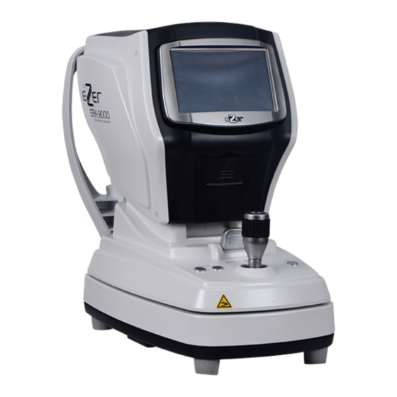
6. Introduction 6.1 Front side of body ① Touch screen Monitor ④ Printer ② Measurement Button ⑦ Chin Rest Up/Down Button ⑤ Stage Holding Knob ⑧ Print Button ③ Joystick ⑥ Power Switch [ Drawing 1] Front Side Name Functions ①... -
Page 23: Back Side Of Body
6.2 Back side of body ① Head Rest ② Measurement ⑤ Height lining mark window ③ Dust Cap ④ Chin Rest [Drawing 2 ] Back Side of Body Name Function ① Head Rest Place the examinee’s forehead against this rest. ②... -
Page 24: Bottom Side Of Body
6.3 Bottom side of body ③ Power IN LET ② Fuse: T2AH 250V ⑦ Under Stage Fixing Bolt ① Stage Clamping Bolt ⑥ USB Connector ⑤ RS-232 Connector ④ EXT Video Connector [ Drawing 3 ] Bottom Side of Body Name Function ①... -
Page 25: Gui(User Interface)
6.4 GUI(User Interface) The user interface was applied to the touch-screen buttons of the ERK-9000. So the user's convenience and speed of operation is improved. The frequently used buttons is located on the left and right of the screen frame. In the measurement mode is commonly used. The remaining modes except measurement modes each mode, please refer to the description page ⑮... - Page 26 The current measuring method indicates the manual( ) or the automatic( ⑥ Manual/Auto measurement. The touch of a button, you switch from manual to automatic or is opposed. Convert Button In the bottom row left to automatically measure the number of measurements is displayed automatically.
-
Page 27: Equipment Installation And Measurement Preparation
7. Equipment Installation and Measurement Preparation 7.1 Plugging - Put ERK-9000 on the table - Connect power cord into power connector - Check power switch OFF (O), plug into electrical outlet 7.2 Release stage fixing [ Drawing 5 ] Stage Clamping Bolt - Rotate stage clamping bolt located in the bottom of body counterclockwise and release - Lift stage holding knob straight up forward to ‘... -
Page 28: Menu Mode
8. MENU Mode The MENU mode on the screen ERK-9000 offers a variety of features that are gathered. Touch a desired function can be executed immediately. The MENU mode 'SETUP-SYSTEM page-MENU MODE' action if the item is set to ON, then run... -
Page 29: Exit ] Touch Button
8.2 [ EXIT ] Touch Button The previous measurements mode or the REF mode to run 8.3 [ REF] / [ KER] / [ RK] / [ CLBC] / [ SIZE] / [ ILLUM] Touch Button Touch the button that corresponds to the measurement and test run mode 8.4 [ DISPLAY] Touch Button Run DISPLAY Mode 8.5 [ SETUP] Touch Button... -
Page 30: Measurement Mode
9. Measurement Mode The main function of ERK-9000 is refractive, keratometry measurement, keratometry/refraction continuous measurement and base curve measurement of contact lens. After enough practice, through model-eye(chapter 9.4) patients should be measured. [ Changing the measurement mode ] The screen left / right in the [MODE] button to touch activated POP-UP window you can select the desired mode. - Page 31 Name Edit Window Cursor Button Switch Button [ Drawing 8] Enter Name Screen Character Input To enter characters by tapping the button that corresponds to a maximum of 16 characters, you can type a letter. Entered the name of the character being added to the edit window of the red cursor to move the cursor one space to the right.
-
Page 32: Rk Mode
9.1 RK Mode RK mode with corneal radius and refraction can be measured. Ring Optical aiming [ Drawing 9 ] RK Mode Screen 9.1.1 Select RK mode a. Described at the beginning of this chapter [The Change of measurement mode] how to select the RK mode by referring. -
Page 33: Print
is measured the same way. b. When the change left, right / left of the icon changes color display. Depending on the icon of the left eye and right eye measurement results are displayed. c. Both left and right eye when measured PD values are displayed on the screen. 9.1.7 PRINT a. -
Page 34: Ref Mode
9.2 REF mode REF mode can be used to measure the refraction. REF measured in the same way as the RK-mode measurements. [ Drawing 11 ] REF Mode Screen 9.2.1 Select REF Mode a. Described at the beginning of this chapter [Change measurement mode] Note how the REF mode. -
Page 35: Ker Mode
9.3 KER Mode KER mode can be used to measure corneal radius. KER measured in the same way as the RK-mode measurements. [ Drawing 12 ] KER Mode Screen 9.3.1 Select KER mode a. Described at the beginning of this chapter [Change measurement mode] Note how the KER mode. -
Page 36: Practice Through The Model Eye
9.4 Practice through the Model Eye Before measuring patients in the product, measured by using a model that should please plenty of practice. 9.4.1 Power ON a. Located in the lower-right corner of the body and turn on the power switch. 9.4.2 Installation a. -
Page 37: Clbc Mode
9.5 CLBC Mode Measure base curves of contact lens in CLBC mode. 9.5.1 Attach contact lens a. Load lens up after dampen convex part of model eye, back side.be careful lens. Contact Lens [ Drawing 14 ] Attachment Contact Lens 9.5.2 Select CLBC Mode a. -
Page 38: Position And Focus
9.5.4 Position and Focus a. Ring image by looking at the screen ring internal / outside mark located near the lever to adjust. b. Ring in the center of the screen when you close Focus light mark will appear near the aiming mark. -
Page 39: Size Mode
9.6 SIZE Mode SIZE mode can be used to measure the diameter of the cornea. Left / Right eye values for the two results can be saved. The measurement of corneal diameter appears on the screen focuses on the patient's eyes are the clearest measure is obtained by pressing the stationary image. The stationary image that you want to measure the diameter of the left and right on target and locate two of the bar diameter can be measured. -
Page 40: Repeated Measurement
b. Measurements of the subjects to the left / right when you are away from the boundary and the boundary with the bar near the bar to touch the places near the border. c. [Left / Right bar Go button to touch the left / right on the border of the bar and place to be measured. -
Page 41: Illum Mode
9.7 ILLUM Mode ILLUM mode with light in the pupil or lens, or cataract state whether there is scratching of the cornea can be observed through the screen. operator, depending on the needs of refraction measurements are also available. Observing light Illumination light Target light Adjustment... -
Page 42: Adjust The Patient's Eye
9.7.2 Adjust the patient's eye a. Patients sit in a chair, then the patient's chin and the forehead is to be expected on the base of the forehead and chin rest. b. Patients to face up to the patient's eye level height chin rest alignment mark to adjust the height of chin rest fit. -
Page 43: Comparison Of Images Through Image List
9.7.6 Comparison of images through image list List screen image left / right eye and stored in a recent left / right eye images for each one (half size, total 2), and the whole image (quarter size, total 4) and shows all on one screen. The selected image is displayed outside the blue box. -
Page 44: The Observing Original Image Through Image View
9.7.7 The observing original image through Image view The Image view Screen is displayed for the original size image and image information. a. Eye through the image of the original size to observe the state. b. If you want to go back to the image list screen [IMAGE LIST] touch button. c. -
Page 45: Display Mode
10. DISPLAY Mode Measured on the screen [DISP] button touch display mode is executed. Display mode stored in the internal memory REF / KER / CLBC measurement results can be verified through the screen. 10.1 Mode Selection On the left side of the screen [REF] / [KER] / [CLBC] touch a button or the right side of the screen, the [DISP] touch buttons (REF KER CLBC sequential change), press select and change the measurement mode and measurement results can be checked . - Page 46 [Drawing 24] Display Mode – KER Page [Drawing 25] Display Mode – CLBC Page...
-
Page 47: Setup Mode
11. SETUP Mode Measurement screen from [SETUP] touch button, you push the User setup mode is executed. User setup mode the DISPLAY, MEASURE, PRINT, SYSTEM, DATE & TIME page footers, and print settings are configured. [ Select page ] Screen left / right of the [DISP] / [MEASURE] / [PRINT] / [SYS] / [DATE & TIME] touch button or the [SETUP] touch button (DISPLAY MEASURE PRINT... -
Page 48: Measure Page
11.2 MEASURE PAGE The [MEASURE] touch button of left side of the screen, you can select the push MEASURE page. [Drawing 27] User setup – MEASURE Page List 11.2.1 SHOOTING MODE The measurement method select from the following: ‘NORMAL’, ‘FAST-3’, ‘FAST-5’ ▪... -
Page 49: Print Page
11.3 PRINT PAGE The left side of the screen, the [PRINT] touch button to push the PRINT page can be selected. [Drawing 28] User Setup – PRINT Page Value List 11.3.1 PRINT TYPE The type of print is selected select from the following: ‘ALL’, ‘IMG’, ‘AVR’, ‘OFF’... -
Page 50: System Page
11.4 SYSTEM PAGE The left side of the screen, the [SYS] touch button to push the SYSTEM page can be selected. [Drawing 29 ] User Setup – SYSTEM PAGE VALUE LIST 11.4.1 MENU MODE The MENU mode of operation when the behavior whether the selection of 'OFF', 'ON' . 11.4.2 KEY SOUND The sound of KEY is selected select from the following: ‘OFF’, ‘MIDDLE’, ‘ON’... -
Page 51: Date&Time Page
11.5 DATE&TIME PAGE The left side of the screen, the [DATE&TIME] touch button to push the DATE&TIME page can be selected. You can change increase or decrease the current value that Years (00-99), month (01-11), a (01-31), time (00-23), minutes (00-59), second (00-59) and '-1', '+1 ',' -10 ',' +10' with push to touch button. The Change of the date and time takes effect immediately and stored separately, are not checked. -
Page 52: Message Page
11.6 MESSAGE PAGE The left side of the screen, the [MSG] touch button can be edited by pressing the print footer and a total of 44 characters (22 characters per line x 2 line) can be entered. Cursor [Drawing 31] Editing Screen Printing Footer [ INPUT THE CHARACTER ] Enter the characters you can type the characters touch. -
Page 53: Self Inspection And Maintenance
12. Self Inspection and Maintenance 12.1 Before Calling a Service Person Warning messages will be displayed on the monitor if some problems occur. It might be operation errors or problems of the machine. In this case, refer the following instructions. If the function is still not salvaged or recovered, disconnect the power supply and consult the dealer. -
Page 54: Replacement Of Printer Paper
(3) Message On Printing Message Cause Remedy Replace the printer paper. NO PAPER Empty printer paper. (refer to ‘12.2 Replacement of printer paper’) 12.2 Replacement of printer paper If a red line appears on the paper, or if ‘NO PAPER’ message is displayed on the screen bottom, please replace printer paper with new one. -
Page 55: Fuse Replacement
12.5 Fuse Replacement The power protection fuse protects the product from excess current. If the power monitoring protection circuit detects excess current, it shut off the current to the equipment in order to prevent overheating and to restrict the SMPS power output. To avoid risk of electric shock, always disconnect the plug from the system prior to fuse replacement. -
Page 56: Service Information
(1) Repair If problem cannot be solved even after taking the measures indicated in section 12.1, contact ERK-9000 representative or distributor for repair. Please refer to the name plate and let us have the following information: ▪ Name of the instrument : ERK-9000 ▪... -
Page 57: Specifications
13. Specifications Refractometry Vertex Distance(VD) 0.0 , 10.0, 12.0, 13.5, 15.0mm Sphere(SPH) -25.00 ~ +22D (VD 12mm) Unit : 0.12 / 0.25 D Cylinder(CYL) 0.00~±10.00D Unit : 0.12 / 0.25 D Axis(AX) 1~180˚ ˚ Unit : 1 Cylinder form -, +, MIX Pupil Distance(PD) 10~85mm Ø2.0mm... -
Page 58: Accessary
14. ACCESSARY [Drawing 35 ] ERK-9000 Accessary Name Standard Quantity ① Power Supply Cable H05VV-F 175mm, 3G 0.75mm², 175mm ② Model Eye Diopters : 1.5168, 110mm X 105mm X 35mm ③ Printing Paper T 12 * 57 * 50 mm 2 rolls ④... -
Page 59: Packing
15. Packing 15.1 Packing Foam Design [Drawing 36 ] ERK-9000 Packing Box 15.2 Packaging step Plastic bag packaging Material : PE Step 1 Size : 0.4Tx750x1300 Color : transparency Foamed polystyrene packaging Material : poly urethane Step 2 Size : 635x650x232.5 ( pair) - Page 60 1. To move alone, holding a fall or be dropped. 2. Holding the rope packing to move your fingers can get hurt. 3. The product is damaged packaging may be damaged, so you must contact manufacturer or dealer. 4. The product contaminated by rain damage or risk of electric shock, so you must contact the manufacturer or dealer.
-
Page 61: Emc (Electromagnetic Compatibility)
EMC (IEC 60601-1-2: 2007) Guidance and manufacturer's declaration - electromagnetic emissions The ERK-9000 is intended for use in the electromagnetic environment specified below. The customer or the user of the ERK-9000 should assure that it is used in such an environment. - Page 62 Guidance and manufacturer's declaration - electromagnetic immunity The ERK-9000 is intended for use in the electromagnetic environment specified below. The customer or the user of the ERK-9000 should assure that it is used in such an environment. Immunity test IEC 60601 test level...
- Page 63 To assess the electromagnetic environment due to fixed RF transmitters, an electromagnetic site survey should be considered. If the measured field strength in the location in which the ERK-9000 is used exceeds the applicable RF compliance level above, the ERK-9000 should be observed to verify normal operation. If abnormal performance is observed, additional measures may be necessary, such as reorienting or relocating the ERK-9000.
- Page 64 Recommended separation distances between portable and mobile RF communications equipment and the ERK-9000 The ERK-9000 is intended for use in an electromagnetic environment in which radiated RF disturbances are controlled. The customer or the user of the ERK-9000 can help prevent electromagnetic interference by maintaining a minimum distance between portable and mobile RF communications equipment (transmitters) and the ERK-9000 as recommended below, according to the maximum output power of the communications equipment.
-
Page 65: Disposal Of Waste Products
17. Disposal of waste products When disposing of the products below to contact us COMPANY : US Ophthalmic Address : 9990 NW Street, Suite 105 Doral, FL33172, US : 888.802.2466 This instrument incorporates a lithium battery, which may pollute the environment if the instrument is disposed.
Need help?
Do you have a question about the ERK-9000 and is the answer not in the manual?
Questions and answers