Table of Contents
Advertisement
Quick Links
Advertisement
Table of Contents

Related Manuals for Eli Ezer ERK-9200


Summary of Contents for Eli Ezer ERK-9200
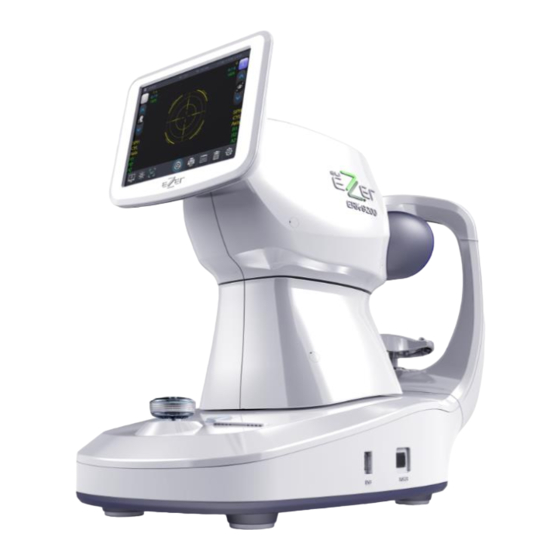
- Page 1 Operation Manual AUTO REF / KERATOMETER ERK-9200...
-
Page 2: Table Of Contents
Table of Contents 1. IMPORTANT NOTICE ........................... 1 1.1 Intended Use ..................................1 1.2 Classifications ..................................1 1.3 Caution ...................................... 2 2. SAFETY ................................3 2.1 SAFETY INFORMATION ..............................3 2.2 Symbol Information ................................4 2.3 General Safety Information .............................. 1 2.4 Cautions in Installation , Storage and Transportion .................... - Page 3 7.7 KP-Diop Dialog ..................................18 7.8 Size Mode ....................................18 7.9 Display Dialog..................................19 8. setting Dialog - Display ........................... 20 8.1 setting Dialog – Measure ..............................20 8.2 setting Dialog – System ..............................21 8.3 setting Dialog – Date ................................ 21 8.4 setting Dialog –...
-
Page 5: Important Notice
The ERK-9200 is classified as IPX0 [Degree of protection against flammability] The ERK-9200 is classified as a device not suitable to be used in a potentially flammable environment. Do not use near flammable materials [Method(s) of sterilization or disinfection recommended by the manufacturer]... - Page 6 No use of the information contained herein. ERK-9200 reserves the right to make changes in its products or product specifications at any time and without prior notice, and is not required to update this documentation to reflect such changes.
-
Page 7: Safety
2. SAFETY 2.1 SAFETY INFORMATION Accessory equipment connected to the analog and digital interfaces must be certificated according to the respective IEC/EN standards (e.g. IEC/EN 60950 for data processing equipment and IEC/EN 60601-1 for medical equipment). Furthermore all configurations shall comply with the system standard IEC 60601-1-2:2014 Everybody who connects additional equipment to the signal input part or signal output part configures a medical system, and is therefore responsible that the system complies with the requirements... -
Page 8: Symbol Information
2.2 Symbol Information Symbol Descriptions TYPE B EQUIPMENT Protective earth (ground) Alternating current Off (power: disconnect to the mains) On (power: connection to the mains) Do not throw away the waste to inappropriate place Crushing hazard sign Hand hazard sign Instruction for user manual Operating instructions CAUTION... - Page 9 Temperature between - 40˚C ~ 70˚C Humidity between 10%RH ~ 95%RH Air pressure between 500hPa ~ 1060hPa...
-
Page 11: General Safety Information
2.3 General Safety Information If you see any warnings or cautions printed on the warning labels, follow the safety instructions in this manual. Ignoring such cautions or warnings while handling the product may result in injury or accident. Be sure to read and fully understand the manual before using this product. -
Page 12: Caution
● In case you leave ERK-9200 without using for certain period, disconnect the power supply and protect the unit with dust cover. ● In case moving this ERK-9200, fix the stage by using clamping bolt and stage holding knob, always keep power off, and then lift the bottom of the unit with both hands. -
Page 13: Environment Of Installing The Device
Avoid installing the device on a place where it is exposed to direct sunlight or near the illumination. Be sure to install the blind when installing the ERK-9200 near to the window. Exposure to the direct sunlight or too bright indoor lights may influence on the... -
Page 14: Patient Environment
① Patient environment (represented by dotted line, extending exactly 1.5 meters) ②ERK-9200 quipment ③④ Peripheral equipment(EN XXXXX and IEC XXXXX) ⑥ Power cord(⑤included protective earth) -
Page 15: External Labels
Wide Dioptric Measurement Range Because the ERK-9200 covers a wide measurement range, from -25D to +22D, even an examinee with strong myopia can be measured. More accurate Measurement The fogging method of the eye fixation target makes examinee’s eye... -
Page 16: Notes For Using The Instrument
3. If you leave ERK-9200 without using for certain period, disconnect the power supply and protect the unit with dust cover. 4. When moving this ERK-9200, fix the stage by using clamping bolt and stage holding knob, always keep power off, and then lift the bottom of the unit with both hands. - Page 17 1. Don’t use organic solvents such as alcohol, thinner, benzene, etc. to clean the surface of this instrument. It may damage the instrument. 2. Do not store alcohol, thinner and other flammable vapors and liquids in the vicinity of this equipment. 3.
-
Page 18: Prerequisites For Safety
5. Prerequisites for safety 5.1 Preparation before use -. Do not operate under direct sunlight or too strong lights -. Do not store alcohol, thinner and other flammable vapors and liquids in the vicinity of this equipment. -. Check the voltage. -. -
Page 19: Introduction
6. Introduction 6.1 Front side of body [ Drawing 1] Front Side Name Functions ① Touch screen Monitor Monitor that displays Measurement ② Jog Dial Measurement button and control of moving ③ Printer Print the measured result ④ Power Switch Switch for turning power ON and OFF [ Chart 1 ] Front side... -
Page 20: Back Side Of Body
6.2 Back side of body [Drawing 2 ] Back Side of Body Name Function Place the examinee’s forehead against this rest. ① Head Rest ② Measurement window Window for the examinee to look at for measurement ③ Dust Cap Anti-dust cap Place the examinee’s chin on the rest. -
Page 21: Bottom Side Of Body
6.3 Bottom side of body [ Drawing 3 ] Bottom Side of Body Name Function ① Fuse: T2AH 250V Protects instrument from the excess electric power. ② RS-232 Connector Connect with PC ③ Power IN LET Connector for the power supply code [ Chart 3 ] Bottom Side of Body... -
Page 22: Gui(User Interface)
7. GUI(User Interface) The user interface was applied to the touch-screen buttons of the ERK-9200. So the user's convenience and speed of operation is improved. The frequently used buttons is located on the left and right of the screen frame. In the measurement mode is commonly used. The remaining modes except measurement modes each mode, please refer to the description page 7.1 Main Dialog 1... - Page 23 ⑤ PD Display of PD(Pupil Distance) results. ⑥ X,Y,Z Displays Current motor position value ⑦ Motor status Displays Current motor status value ⑧ Focusing button Control of Focusing [ Chart 4 ] Operation Button...
-
Page 24: Main Dialog 2
7.2 Main Dialog 2 [ Drawing 4-2 ] Touch Screen 2 Name Function ① Motor initial Touch to go for motor initial positiont. position ②. Measurement A1 : Auto measurement of monocular vision. A2 : Auto measurement of binocular vision. Mode 1 M : Manual measurement ③... -
Page 25: Illum Dialog
7.3 ILLUM Dialog Name Function ① ILLUM Display Selects a measurement of ILLUM. mode ②. Control Panel for Control of VD, REF, ILM, TAR value. ILL parameter... -
Page 26: Kp Dialog
7.4 KP Dialog You start measurement in KP Mode, measure the Kerator value of the center and then measure the Kerato value of 4 position (up, down, left, right). Name Function ①KP Display Display of KP mode. mode ②.Measurement Display of measurement direction Direction Mode ③... -
Page 27: Kp-Ker Dialog
7.5 KP-Ker Dialog Display of KER measument result. 7.6 KP-ECC Dialog Display of ECC measument result. -
Page 28: Kp-Diop Dialog
7.7 KP-Diop Dialog Display of Diop measument result. 7.8 Size Mode In size mode, you can select Auto or Manual and adjust the ThreshHold value... -
Page 29: Display Dialog
Display Dialog Show the measured value. ① Print the measured value. ② It shows KER / REF / CLBC value. -
Page 30: Setting Dialog - Display
8. setting Dialog - Display ① STEP : Unit of measurement value. ② CYL Sign : Setting +, - or ± ③ VD : Setting : 0 / 10.0/ 12.0/ 13.5/ 15.0 VD value ④ KERATO Format : Setting format of Radius or Diopt ⑤... -
Page 31: Setting Dialog - System
8.2 setting Dialog – System ① Language: Setting Language ② Lcd Invert: Setting LCD invert on or off ③ Start Position: 3 axis motor initial position ④ Init After Measure: Select whether to move to initial position after measurement ⑤ LCD Bright: Setting LCD brightness5. Screen Off: ⑥... -
Page 32: Setting Dialog - Print
8.4 setting Dialog – Print ① Print Type : Setting All/ IMG/ AVR/ OFF ② Print No. : Print paper stack number ③ Auto Cutting : Setting OFF/ Half cut/ Full cut ④ Data Format : Setting of print date format. ⑤... -
Page 33: Align Dialog
9. Align Dialog ① LED status change button (Ker, Ref, Af, Aim, Align, Chart, Ext) ② LED status change button (Ker Peri Led) ③ LED brightness setting ④ Ker ⇔ Ref switch button ⑤ Shutter On / Off ⑥ Button Status Indicator (It will be highlighted when the button is pressed.) ⑦... -
Page 34: Ref Tune Dialog
③ Test the Fog motor repeatedly. ④ Shows the current key status. (When pressed, it is reversed.) ⑤ Initialize the Fog motor. ⑥ Move the Fog motor. ⑦ Move the Fog motor. ⑧ Adjust the chart LED brightness value. ⑨ Fog Set the initial value of the motor. ⑩... -
Page 35: Ref Tune Result
9.3 Ref Tune Result 9.4 Ker Tune Dialog ① Exit without saving ② Set the KER model eye value. ③ Start Ker Tuning button ④. Currently set model eye value ⑤ Save the set value and exit ⑥ View Ker Tune Result... -
Page 36: Ker Tune Result
9.5 Ker Tune Result Turn off the power after connecting or disconnecting the power cable. Do not operate the unit with wet hands. Otherwise, to cause death or serious injury can result in electric shock. -
Page 37: Print Mode
10. Print Mode -. Pressing the touch button( ) to print the measured results. will be printed when you print. -. Depending on the user setup mode is selected in different prints. [ Drawing 10 ] Print Sample Iris has damaged on Some of IOL patient. If damage is deep, measurement result may have some error. -
Page 38: Self Inspection And Maintenance
11. Self Inspection and Maintenance 11.1 Before Calling a Service Person Warning messages will be displayed on the monitor if some problems occur. It might be operation errors or problems of the machine. In this case, refer the following instructions. If the function is still not salvaged or recovered, disconnect the power supply and consult the dealer. - Page 39 (3) Message On Printing Message Cause Remedy NO PAPER Empty printer paper. Replace the printer paper. (4) Error during measurement Error Cause Remedy -. If you pass the other eye One eye -. You can not move to the other measured eye.
-
Page 40: Fuse Replacement
11.2 Fuse Replacement The power protection fuse protects the product from excess current. If the power monitoring protection circuit detects excess current, it shut off the current to the equipment in order to prevent overheating and to restrict the SMPS power output. To avoid risk of electric shock, always disconnect the plug from the system prior to fuse replacement. -
Page 41: Service Information
(1) Repair If problem cannot be solved even after taking the measures indicated in section 12.1, contact ERK-9200 representative or distributor for repair. Please refer to the name plate and let us have the following information: ▪ Name of the instrument : ERK-9200 ▪... -
Page 42: Specifications
12. Specifications Refractometry Vertex Distance(VD) 0.0 , 10.0, 12.0, 13.5, 15.0mm Sphere(SPH) -25.00 ~ +22D (VD 12mm) Unit : 0.12 / 0.25 D Cylinder(CYL) 0.00~±10.00D Unit : 0.12 / 0.25 D 1~180˚ ˚ Axis(AX) Unit : 1 Cylinder form -, +, MIX Pupil Distance(PD) 10~85mm Minimum Pupil Diameter... -
Page 43: Accessary
13. ACCESSARY [Drawing 35 ] ERK-9200 Accessary Name Standard Quantity ① Power Supply Cable H05VV-F 175mm, 3G 0.75mm², 175mm ② Model Eye Diopters : 1.5168, 110mm X 105mm X 35mm ③ Printing Paper T 12 * 57 * 50 mm 2 rolls ④... -
Page 44: Packing
14. Packing 14.1 Packing Foam Design [Drawing 36 ] ERK-9200 Packing Box [Drawing 37 ] ERK-9200 Packing Box Sticker... -
Page 45: Packaging Step
14.2 Packaging step Plastic bag packaging Material : PE Step 1 Size : 0.4Tx750x1300 Color : transparency Foamed polystyrene packaging Material : poly urethane Step 2 Size : 635x650x232.5 ( pair) Color : Silver Paper box packaging Material : KLB225.CK.K.CK.KLB225 Step 3 Size : 635x650x465 Color : 1 degree black, yellow... -
Page 46: Emc (Electromagnetic Compatibility)
The Electromagnetic Compatibility Directive sets the essential requirements for electrical and electronic equipment that may disturb or even be disturbed by other equipment. The ERK-9200 complies with these requirements as tabled below. Follow the guidance on the tables for use of the device in the electromagnetic environment. - Page 47 0 % U : 0.5 cycle At 0°, 45°, 90°, 135°, 180°, 225°, 270° and 315° IEC 61000-4-11: 0 % U ; 1 cycle Voltage dips AC Mains 2004 70 % U ; 25/30 cycles Single phase: at 0º IEC 61000-4-11: Voltage interruptions AC Mains 0 % U...
-
Page 48: Disposal Of Waste Products
16. Disposal of waste products When disposing of the products below to contact us COMPANY : US Ophthalmic Address : 9990 NW 14 th Street, Suite 105 Doral, FL33172, US : 888.802.2466 This instrument incorporates a lithium battery, which may pollute the environment if the instrument is disposed.
Need help?
Do you have a question about the ERK-9200 and is the answer not in the manual?
Questions and answers