Table of Contents
Advertisement
Quick Links
Advertisement
Table of Contents

Related Manuals for Fast Lokal 400


Summary of Contents for Fast Lokal 400
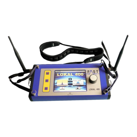
- Page 1 Lokal 400 Operating Manual Lokal 400 Operating Manual Page 1...
-
Page 2: Table Of Contents
8.4. Filter setting ..........................23 8.5. Saving and uploading measurement series ................24 Connection the LOKAL 400 device with a PC ................... 25 Charging the device ......................... 25 Troubleshooting ..........................26 Cleaning, maintenance, and transport .................... 28 Lokal 400 Operating Manual... -
Page 3: Safety Instructions
Please read these instructions in full before the LOKAL 400 device is put into operation for the first time. For reasons of safety and CE compliance, you may not carry out any changes or modifications on the... -
Page 4: Scope Of Delivery And Accessories
MB4 directly to Lokal 400 Ground microphone with spiral cable 10 3-fold charger for Lokal 400 central unit and Testrod with extensions MB´s in the same time Adapter for headphones to be connected to... -
Page 5: Control Elements
Turn the dial to access the menu and setting functions and to specify already 13 Cover for charging jack (IP65) selected settings. Press the dial to confirm any selection or 14 Microphone jack setting. 15 Aerial connection right Aerial connection left Lokal 400 Operating Manual Page 5... -
Page 6: Powering Up And Operating The Device
If you wish to connect a sensor to the LOKAL 400 device, please use the sensor jack [see Chapter 4, legend item no. (7)]. A more detailed description of the different sensors and their particular fields of application is stated below. -
Page 7: Powering Up For Electroacoustic Listening
5.2. Powering up for electroacoustic listening Headphones: Connect the headphones to the headphones jack of the LOKAL 400 device [see Chapter 4, legend item no. (7)], if required. Please use the original headphones only as they have been designed specifically for acoustic leakage detection purposes and feature certain leakage-borne noise identification capabilities. -
Page 8: Control And Menu Structure
6.1. Control The Lokal 400 device features menu items and selection boxes which can be activated either directly through the touch screen or with the dial. If you wish to operate the device with the touch screen, just press your finger on the requested menu item or selection box. -
Page 9: Settings
”Cancel“ key. 6.3.2. Language [2] The Lokal 400 system offers a number of display languages. Please scroll down until you reach the language you request and confirm the selection of this language by pressing the right dial. - Page 10 Institutions for Statutory Accident Insurance and Prevention) are fully met when operating the original headphones (part of the delivery). For individual adjustment of the noise level, the LOKAL 400 device offers a scale ranging from 1 (relatively low noise level) to 3 (maximum noise level), with any setting still being in full compliance with VGB 121 requirements.
- Page 11 C “Sensor entry“ A, B, and C are the channels of the measurement boxes (A =red; B=blue; C=yellow), and “Sensor entry“ indicates the direct connection of any microphone (see Chapter 5, Section ”Sensors“) to the Lokal 400 central unit. These settings can also be made through the correlation main window.
-
Page 12: Automatic Measurement
7 Searching for a leakage by correlation The LOKAL 400 is capable of calculating the precise position of a leakage (correlation). In order to do so, please proceed as described in Chapter 5.1 “Powering-up for correlation“ and closely follow the hints concerning the different types of sensor, the measurement boxes, and the signal entries. -
Page 13: Manual Measurement
Up to 20 different pipe sections can be entered into the LOKAL 400 device. If a pipe consists of mixed materials and/or features varying diameters, just enter the materials one by one into the table starting at measurement box A (red). If you wish to delete any input, you can either press the button “line“ [6] or select ”... -
Page 14: Setting Options For Correlation (Correlation Main Window)
[10] Coherence (FFT) for A and B [11] Frequency illustration (FFT) for Channel B [12] Amplification Channel B [12.1] numerical value (0-100%) to amplify Channel B [13] Number of completed average determinations [14] DELTA T in milliseconds LOKAL 400 Operating Manual Page 14... - Page 15 In the first case, the system will go back to the start screen; in the latter case, the system will go back to the correlation main window. LOKAL 400 Operating Manual Page 15...
- Page 16 “Measurement box” button [2], the TIPP: If you press on this LOKAL 400 system will automatically adjust the amplification level. 7.3.3. Correlation results If a measurement is stopped either after the maximum average determinations have been completed (50 determinations in the automatic mode and 250 determinations in the manual mode) or by tapping on the “Stop”...
-
Page 17: Receiving Radio Data
Chapter 7.3 [6]] whether or not the data issued by a transmitter (measurement box) is being received by the LOKAL 400 central unit. If the data is being received, the icons are displayed as shown in the example. If data reception is interrupted [for possible reasons please see Chapter 11 “Troubleshooting“], the icons are crossed with a black X. - Page 18 In rare cases, it might happen that the sound velocity of the pipe-section is not the same than the one stored in the Lokal 400. The reason for this could be the age of pipelines (i.e. hardening of the material in plastic pipes) or incrustations (i.e.
-
Page 19: Acoustic Leakage Detection
The window where the sensitivity of the sensor can be adjusted will open up, and a scale ranging from 0 to 100% will be displayed where the currently set amplification of your LOKAL 400 Operating Manual Page 19... - Page 20 Pressing the dial or pressing the Amplification icon again activates the set amplification level. TIP: If the amplification menu is called and if this button is pressed for a little while, the LOKAL 400 system will choose the optimal amplification level automatically. As soon as the operator hears several beeps while the button is pressed, the button can be released and the system will choose the most suitable amplification level.
-
Page 21: Measurement Modes
The measurement mode symbol (1) in the measurement indication window shows the mode currently set. Pressing the dial (3) calls the requested measurement mode: (2) Smart mode (3) Volume mode LOKAL 400 Operating Manual Page 21... - Page 22 As a rule of thumb, you can say: “The closer the leakage, the higher is the Smart indicator bar and the brighter is its color.“ LOKAL 400 Operating Manual Page 22...
-
Page 23: Deleting The Current Measurement Series
8.3. Deleting the current measurement series The Lokal 400 device is capable of carrying out up to seven measurements simultaneously as a measurement series. This measurement series can be displayed in the measurement indication window. -
Page 24: Saving And Uploading Measurement Series
NOTE: Changing the filter setting will result in the current measurement series to be deleted ! Automatic: The Lokal 400 system is capable of optimizing the filter settings automatically. In order to do so, please open the window for the frequency range indication and keep this button pressed for a little while. -
Page 25: Connection The Lokal 400 Device With A Pc
9. Connection the LOKAL 400 device with a PC The Lokal 400 device can be connected with a PC via the provided USB cable. If the LOKAL 400 program has been installed on the PC, the saved data can be transferred to the PC where you can subsequently change the measurement parameters [pipe material, length, and diameter]. -
Page 26: Troubleshooting
No signal received from 2. Aerials have not been mounted Use the provided aerials for the LOKAL 400 device measurement boxes to central unit 3. Aerials have not been mounted Use the provided aerials for the measurement boxes to the measurement boxes 4. - Page 27 Customer Service department. Display remains black after 1. Battery is empty Recharge the battery of the Lokal 400 device the device has been 2. Defective central unit Please contact our Customer Service department...
-
Page 28: Cleaning, Maintenance, And Transport
Storage and transportation • We recommend using the original FAST transport case for the LOKAL 400 device and its accessories if you need to shuttle the equipment from one place to the other. This case has perfect cavity inserts for the particular components. The picture below may serve as an example of the arrangement of the equipment in the FAST case. - Page 29 -20°C and +60 °C; storage: between -25 °C and +65 °C Dimensions (approx.) L 225 x W 165 x H 100mm Weight (approx.) 2,900 grams Technical data Accelerometer sensors Microphone Piezoceramics Safety class IP 68 LOKAL 400 Operating Manual Page 29...
- Page 30 The frequency and the material of the pipes play a major role as far as the distance the sound travels is concerned. As is the case with ground-borne sound, low-frequency sounds travel further distances, and softer materials like PVC or PE pipes absorb the energy caused by the leak more strongly than metallic pipes. LOKAL 400 Operating Manual Page 30...
- Page 31 Always make sure that the distance between any two points that you have selected for the ground microphone are not too far apart as otherwise you might miss the leak. As a rule, the distance apart should not be more than one metre. LOKAL 400 Operating Manual Page 31...
Need help?
Do you have a question about the Lokal 400 and is the answer not in the manual?
Questions and answers