Advertisement
Quick Links
Advertisement

Related Manuals for Core Health & Fitness Star Trac 8TR


Summary of Contents for Core Health & Fitness Star Trac 8TR
- Page 1 CORE HEALTH & FITNESS 8TR / 8TRx Treadmills ls ASSEMBLY MANUAL...
- Page 2 TABLE OF CONTENTS IMPORTANT SAFETY INSTRUCTIONS ........................2 PRODUCT SPECIFICATIONS ........................4 ASSEMBLY ........................5 SUPPORT & SERVICE ........................17 Page 1...
-
Page 3: Important Safety Instructions
IMPORTANT SAFETY INSTRUCTIONS WARNING! Before using this product, it is essential to read the ENTIRE Owner’s Manual and ALL installation instructions. The Owner’s Manual describes equipment setup and instructs members on how to use correctly and safely. Read all warnings posted on the machine. Health related injuries may result from incorrect or excessive use of exercise equipment. - Page 4 Do not exceed the maximum allowable weight limit of: • 8TRx - 500 lbs. / 227 kg. • 8TR - 500 lbs. / 227 kg. Familiarize yourself with the location of the STOP buttons on the console. If you experience diffi...
-
Page 5: Product Specifications
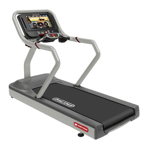
PRODUCT SPECIFICATIONS Fig. 2 Pictured: 8TRx with 19” OpenHub Embedded Console SKU: 9-9291 110V Desc: 8TRx Treadmill 9-9294 220V CE/UL/FCC/CSA Max User Unit Weight Width Length Height Belt Width Weight 0-500 lbs 0-226 kg SKU: 9-9281 110V Desc: 8TR Treadmill 9-9284 220V, UL/FCC Max User Unit Weight... -
Page 6: Assembly
ASSEMBLY Required Tools: • Metric Socket Set • Metric Allen Key Set • #2 Phillips Screwdriver • 1/2” Open-ended Wrench • 13mm Open-ended Wrench Please note that all images are of the 8TRx unless otherwise noted. PROCEDURE 1. Unpack all parts and inspect for damage. - Page 7 4. Slide the left side handrail grommet down onto the left handrail - please note that the grommets are left-right specifi c. 8TR: Skip this step, the grommets on the 8TR are pre-installed onto the handrails. Fig. 5 5. Slide a beauty ring onto the left handrail.
- Page 8 6. Use a 1/2” open-ended wrench to secure the left side handrail to the frame using three (3) 5/16” x 3/4” hex head fl ange screws - DO NOT FULLY TIGHTEN. Fig. 7 8TR: Please see Figure 8 - Use a 1/2” open-ended wrench to secure the left side handrail to the frame using four 5/16”...
- Page 9 9. Install the mast grommet onto the mast - note that the grommet is orientation- specifi c. Fig. 10 10. Install the mast into the frame and pull the ends of the cables from the mast into the motor compartment. Fig.
- Page 10 11. Use a 1/2” open-ended wrench to secure the mast to the frame using two (2) of the 5/16” x 3” hex head fl ange screws and two (2) 5/16” x 3/4” hex Fig. 12 head fl ange screws - DO NOT FULLY TIGHTEN.
- Page 11 13. Install the top rail into the left and right handrails. CAUTION: Be careful not to pinch or damage the hotbar cables while installing the top rail. Fig. 15 14. Use a 4mm allen key to secure the top rail to the left handrail using two (2) of the M6 x 25mm button head cap screws - DO NOT FULLY TIGHTEN.
- Page 12 17. Install the console weldment grommet onto the console weldment. Fig. 18 18. Install the console weldment onto the top rail, then pull the mast cable bundle through the console weldment. CAUTION: Be careful not to pinch the hotbar cables while installing the display weldment.
- Page 13 20. Use a 13mm open-ended wrench to secure the console weldment to the hotbar using two (2) of the M8 x 35mm hex head fl ange screws. Fig. 21 21. Use a 6mm allen key to secure the top mast bezel to the mast using two (2) M8 x 65mm socket head cap screws - DO NOT FULLY TIGHTEN.
- Page 14 23. Use a 6mm allen key to fully tighten the screws from Steps 21-22. Fig. 24 24. Use a 4mm allen key to fully tighten the screws from Steps 14-15. Fig. 25 25. Use a 1/2” open-ended wrench to fully tighten the screws from Steps 6-7.
- Page 15 26. Slide the left side bed cover into position. Fig. 27 27. Push the front end of the side bed cover forward into the handrail while tucking the fi nger guard under the belt. Lift the center of the side bed cover up, to create a bow, and slide the lip of the rear side bed cover under the rear end 28.
- Page 16 30. Connect the data (A) and I/O (B) cables to the MCB as indicated in Figure 25. Fig. 30 31. Re-seat the nose cap by pushing it back into place, then secure it in place by using a #2 phillips screwdriver to tighten the six (6) screws from Step 8.
- Page 17 33. Use a #2 phllips screwdriver to secure the left side cover retaining plate to the frame using one (1) of the 10-24 x 3/4” pan head machine screw. 8TR: Please see Figure 34 - Use a #2 Fig. 33 phllips screwdriver to secure the left side cover retaining plate to the frame using one (1) of the 10-24 x 3/4”...
- Page 18 36. Slide the mast and side rail grommets down into position and ensure they are tightly seated between the weldments and the shrouds/covers. Fig. 36 37. Refer to document 620-8387 contained with the console documentation to connect the treadmill cables to the console front.
- Page 19 39. Plug the power cable into the power inlet located on underneath the motor compartment - be sure to pass the cable through the power cord retention clamps. 8TR: Please see Figure 39 - Install the power cord into the front of the machine, then tighten the ziptie to secure the power cord in place.
- Page 20 41. Perform a Speed Calibration: On the numeric keypad, press and hold the keys together. The Service Menu will display. A beep will sound and “MAINTENANCE MODE” will display momentarily in the Information Window. Release all keys. “SERIAL NO #####” will display in the Information Window. Use the incline keys to navigate.
-
Page 21: Support & Service
SUPPORT & SERVICE For Technical Support, Service, Parts Orders or any Customer Service needs, please contact us direct by phone, email, or through our 24 hour support site: GLOBAL SUPPORT CENTER 4400 NE 77th Avenue, Suite 300 Vancouver, WA 98662 Tel: (360) 326-4090 •... - Page 22 THIS PAGE INTENTIONALLY BLANK Page 21...
- Page 23 PART NUMBER 620-8793, REV B © 2021 CORE HEALTH & FITNESS LLC All rights reserved. Star Trac, the Star Trac logo and StairMaster are registered trademarks of Core Health & Fitness, LLC. Schwinn and Nautilus are registered trademarks of Nautilus Inc. used under license to Core Health & Fitness LLC. Throwdown is a registered trademark of Throwdown Industries, LLC.
Need help?
Do you have a question about the Star Trac 8TR and is the answer not in the manual?
Questions and answers