Table of Contents
Advertisement
Quick Links
Advertisement
Table of Contents

Related Manuals for SSS Siedle TR 602 Series


Summary of Contents for SSS Siedle TR 602 Series
- Page 1 Planning and system manual for access control Issue 2021...
-
Page 2: Table Of Contents
Contents 1 Planning help 7.1 Installation EC 602-… 8 Programming 2 Configuration examples Basic circuit diagram EC 602-… 8.1 General 3 Function overview Basic circuit diagram 8.2 Stand alone operation EC 602-… + ECE 602-… 4 Safety remarks 8.3 Operation with entrance (Maximum configuration) controller EC 602-…... - Page 3 Remarks This document serves as a guide for the planning and technical imple- mentation of a Siedle access control system. It is designed to provide an overview of the key points that need to be observed. This document supplements and is supplemented by the system manuals for the following Siedle door communication systems:...
-
Page 4: Planning Help
1 Planning help Access control requirements vary Find the right access control in depending on the type and function just four steps: of the building. This planning help is designed to help you quickly identify the right 1. What are my access control system for you. - Page 5 1. What are my requirements? Number of users? £ 1–9 £ 10–99 £ 100–499 £ > 500 Number of doors to be con- £ 1 trolled? £ 2–8 £ > 8 Stand-alone or networked £ Stand alone operation operation? £ Networked operation (see description below) Stand alone operation Networked operation...
- Page 6 1 Planning help 2. Which expansion stage is right for me? (pre-selection) Number of users 1–9 10–99 100–499 > 500 A / B A / B 2–8 A / B > 8 The selection of the expansion stage is a pre-selection. After selecting the input/read unit(s) that you want to use, you can use this preselection to help determine the system that...
- Page 7 3. Which input/read unit(s) do I want to use? The following input/read units are currently available for selection: COM 611-02 ELM 600-0 FPM 600-0 In the case of the code lock module, The electronic key reading module The fingerprint module is based on the door release is triggered by is the read unit for access control biometrics: The user‘s fingerprint is...
- Page 8 1 Planning help 4. Which configuration (expansion stage + input/read unit) makes sense for me? (recommendation) Upgrade stage Operation with Networking several Operation with Secure Operating mode Stand alone operation entrance controller Secure Controller Controller SC 600-… EC 602-… SC 600-… Detached home, individual rooms Predominating Detached home/...
- Page 9 Upgrade stage A Upgrade stage B = Stand alone operation = Operation with entrance controller EC 602-… Characteristics: • 1 access point is controlled. Characteristics: • With FPM 611-… up to 100 users • Up to 8 access points can be • With ELM up to 9 users controlled with the fully extended •...
-
Page 10: Configuration Examples
2 Configuration examples Detached house with fingerprint module (FPM) Starting situation Remarks • When using an FPM 600-…, we • Detached family home, • To prevent burglaries, we rec- recommend reading in two user Family with 1 child (3 users) ommend the use of a motorised fingerprints per user. - Page 11 Stand alone max. 100 Recommendation – Pilfer safeguard In stand-alone operation, the switching contact for opening the DSC 602-… door is located in the device. TR 602-… If the read unit is in an unpro- tected outdoor area or a publicly accessible area, we recom- mend using a pilfer safeguard (DSC 602-… + ZDS 601-…) to pro-...
- Page 12 2 Configuration examples Detached house with code lock module (COM) Starting situation Remarks You can find further information • Detached family home, • To prevent burglaries, we rec- about the individual products in Family with 2 children ommend the use of a motorised the detailed function overview.
- Page 13 max. 99 Further input/read units possible on the same door Convenience option: Programming using The EC 602-… entrance controller PRS 602-… and allows several input/read units to be PRI 602-… USB combined on one door station (e.g. COM). If more than 2 door stations are to be managed (up to 8), the ECE 602-…...
- Page 14 2 Configuration examples Apartment block with code lock module (COM) Starting situation Remarks You can find further information • Multiple family home, 3 tenants • To prevent burglaries, we rec- about the individual products in (e.g. multi-generation house) ommend the use of a motorised the detailed function overview.
- Page 15 EC + ECE max. 99 Further input/read units possible on the same door Convenience option: The EC 602-… entrance controller Programming using allows several input/read units to be PRS 602-… and combined on one door station (e.g. PRI 602-… USB COM). The EC 602-…...
- Page 16 2 Configuration examples Commercial building/access to individual offices with electronic key reading module (ELM) Starting situation Remarks You can find further information • Small company with up to • To prevent burglaries, we rec- about the individual products in 9 employees ommend the use of a motorised the detailed function overview.
- Page 17 Stand alone max. 9 Recommendation – Pilfer safeguard In stand-alone operation, the switching contact for opening the DSC 602-… door is located in the device. TR 602-… If the read unit is in an unpro- tected outdoor area or a publicly accessible area, we recom- mend using a pilfer safeguard (DSC 602-… + ZDS 601-…) to pro-...
- Page 18 2 Configuration examples Industrial buildings with electronic key reading module (ELM) Starting situation Remarks You can find further information • Industrial building with up to • To prevent burglaries, we rec- about the individual products in 500 employees ommend the use of a motorised the detailed function overview.
- Page 19 max. 899 Further input/read units possible on the same door Convenience option: Programming using The EC 602 allows several input/read PRS 602-… and units to be combined on one door PRI 602-… USB station (e.g. COM). If more than 2 door stations are to be managed (up to 8), the ECE 602-…...
- Page 20 2 Configuration examples Industrial buildings with electronic key reading module (ELM) Starting situation Remarks You can find further information • Industrial building with up to • To prevent burglaries, we rec- about the individual products in 500 employees ommend the use of a motorised the detailed function overview.
- Page 21 SC 600-... max. 4 max. 500.000 max. 16 Further input/read units possible on the same door The SC 600 Secure Controller allows several input/read units to be combined on one door station (e.g. COM). When operated with the Siedle Vario bus protocol, up to 8 read/ input units of the same type can be SC 600-…...
- Page 22 2 Configuration examples Industrial buildings at several locations, with electronic key reading module (ELM) Starting situation Remarks You can find further information • Industrial building with • To prevent burglaries, we rec- about the individual products in 500 employees or more, distributed ommend the use of a motorised the detailed function overview.
- Page 23 SC 600-... > 500 SC 600-… SC 600-… NG 706-… NG 706-… NG 706-… NG 706-… TR 603-… TR 603-… ELM… ELM… ELM… ELM… ELM… Location B ELM… Location A Example in the configurator Components required Direct link Secure Controller SC 600-… Configuration number: K21184611 2x (4x) Line rectifier NG 706-...
-
Page 24: Function Overview
3 Function overview Detailed overview of the expansion stages Component/ property Stand alone operation EC 602-… + ECE 602-… max. 2 + 6 (max. 8) ü ü (max. 8 ELM) Max. 9 RFID cards or RFID Max. 899 RFID cards or RFID tags tags (electronic key) (electronic key) can be read + 1 Master –... - Page 25 Component/ property SC 600-… max. 4 Doors ü (max. 8 ELM) ü (max. 8 COM) (Up to 500.000 users) ü (Access groups and time profiles/week programmes) ü (not yet active) ü max. 128 Gateways Networking max. 64 SC 600-… Number of 4 Switching switching contacts contacts 3 Control outputs...
- Page 26 3 Function overview Detailed overview of the expansion stages Component/ property Stand alone operation EC 602-… + ECE 602-… Number of – 2 Switching inputs switching inputs Number of input/ Max. 8 per device type read units Individual, stored – ü factors can be deleted Programming manually...
- Page 27 Component/ property SC 600-… Number of 8 Switching inputs switching inputs Number of input/ Max. 16 read units Individual, stored ü factors can be deleted Programming Via administration interface Several input/ ü read units can be combined...
- Page 28 3 Function overview Information about components and properties Electronic-key reading module Gateway/cascade control for Device configuration (guided ELM 600-… 2 door releases commissioning) ELM can be used for both stand- The door release contacts are trig- (only for operation with SC 600-…) alone operation or with a controller gered one after the other within a The Secure Controller‘s commis-...
-
Page 29: Safety Remarks
4 Safety remarks Burglary protection unauthorized attack from inside and Standard 12 V AC door releases are outside. not regarded as a locked door by insurance companies. In the event of Safety remark! Mounting, installation and servicing a burglary, damage is not generally All data connections to an work on electrical devices may only covered. -
Page 30: Establishing Access Control With Vario Bus
5 Establishing access control with Vario bus Installation notes The Vario bus is the bus system for Telecommunication cables must be Siedle access control and connects used for installation. its system components to one J-Y(St)Y Twisted pair conductors, another. shielded In addition, “digital calls”... -
Page 31: Power Supply
Power supply The Vario bus system components can be supplied with the following power supply: Models /Power supply TR 602-… TR 603-… VNG 602-… (12 V AC) * (12 V AC) * (30 V DC) Input/read unit ELM 600-… ü ü ü FPM 600-… ü ü COM 611-… ü ü Controller EC 602-…... -
Page 32: Range
5 Establishing access control with Vario bus Range The maximum range of the Vario Star-shaped installation Data line range bus varies between the supply line In the case of the star-shaped instal- Each controller (EC 602-… / and data line. lation, each input/read unit is sup- SC 600-…) provides the connection plied by a separate line. - Page 33 max. 260 m ELM 600/611-… TR 602-… EC 602-… Vario bus address: 1 max. 260 m ELM 600/611-… Vario bus address: 2 FPM 611-… TR 603-… Vario bus address: 3 max. 130 m Vario bus: Supply line, 2 cores Data line, 2 cores Range of the supply line for star- All specifications relating to ranges shaped installation of the supply line...
- Page 34 5 Establishing access control with Vario bus Range TR 602-… EC 602-… max. 130 m ELM 600/611-… COM 611-… Vario bus address: 1 Vario bus: Supply line, 2 cores Data line, 2 cores Range of the supply line for bus All specifications relating to ranges installation of the supply line with refer to the above mentioned con-...
-
Page 35: Input/Read Units
6 System components Input/read units COM 611-02 ELM 600-0 Code lock module as an input unit Electronic key reading module with for entering codes for door calls and MIFARE DESFire EV2 technology as control functions in conjunction with contactless access control system the Siedle Vario bus. - Page 36 6 System components RFID card / RFID tag (electronic key) EKC 600-0 / EKC 600-01 EK 600-1 Electronic key card in conjunction Electronic key in conjunction with with the Siedle electronic key the electronic key reading modules. reading modules. Each electronic key is unique, com- EKC 600-0 contains 2 transponders pletely encapsulated and works for ELM 600-…...
- Page 37 Compatibility matrix EK 600-01 EKC 600-01 EK 600-0 EKC 600-0 ü Compatible (As of (As of – Not compatible 11/2018) 11/2018) ü * Compatible, however all old EK/ EKC 601-… must be replaced with ELM 611-01 – – ü ü new EK/EKC 600-… to be able to ELM 611-02 –...
-
Page 38: System Components Ec
6.1 System components EC 602-… Controller and expansion EC 602-03 ECE 602-0 ZRCE 602-0 Entrance controller in switch panel Entrance controller extension in Ribbon cable, each with plug at housing for code lock module, switch panel housing. Upgrades the either end (appr. 35 cm long). For electronic key reading module or fin- EC 602-…... -
Page 39: Power Supply
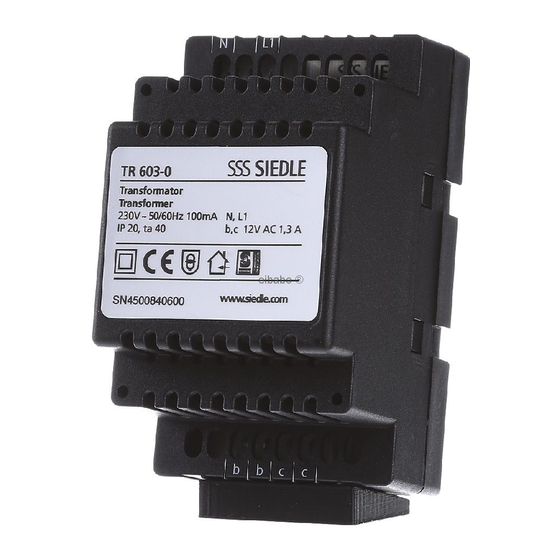
Power supply TR 603-0 TR 602-01 Transformer in switch panel housing Transformer in switch panel housing for supplying system and additional for supplying system and additional components. components. Performance features: Operating voltage: 230 V AC, • Thermal protection +/-10 %, 50/60 Hz • Double terminals (secondary) Operating current: 170 mA •... -
Page 40: Programming - Ec 602
6.1 System components EC 602-… Programming – EC 602-… PRI 602-01 USB ZWA 640-0 The programming interface Western socket accessory for switch PRI 602-… USB in a switch panel panel mounting. Integrated socket housing connects a Windows PC via for 4/6/8-pin western plug. the USB port to the Siedle In-Home Protection system: IP 20 bus and the Siedle Vario bus. -
Page 41: Space Requirement In The Distributor
Space requirement in the distributor Models Unit width EC 602-… ECE 602-… TR 603-… TR 602-… NG 602-… PRI 602-… USB ZWA 640-… PRS 602-02 VBPS 602-02 Programming software suitable for Vario bus protocol software for programming the Vario bus com- logging telegrams on the Siedle ponents. Variobus, e.g. for monitoring Siedle System requirements: access control. -
Page 42: Installation General Information
7 Installation General information Installation Siedle access control is an inde- pendent system which can be oper- ated in parallel to a door communi- cation system. The code lock module can be used in parallel operation with access control and the intercom system to enter codes and also make door calls. -
Page 43: Basic Circuit Diagram, Stand-Alone Operation With Elm 600/611
7 Installation Basic circuit diagram, stand-alone operation with ELM 600/611-… and DSC 602-… Tö Device ZDS 601-… TR 602-… DSC 602-… requirement ELM 600/611-… Remarks a), b), c), d) Notes on the circuit diagram d) ELM are only functional when installed. a) Pilfer safeguard for installation For ELM in the Siedle Vario design in the MR 611-…... -
Page 44: Basic Circuit Diagram, Stand-Alone Operation With Fpm 600
Basic circuit diagram, stand-alone operation with FPM 600-… and DSC 602-… Tö Device ZDS 601-… TR 602-… DSC 602-… requirement FPM 611-… Remarks a), b), c) Notes on the circuit diagram a) Pilfer safeguard for installation in the MR 611-… mounting frame. For tamper-proof operation of the read unit. -
Page 45: Basic Circuit Diagram Ec 602
7.1 Installation EC 602-… Basic circuit diagram EC 602-…... - Page 46 Supplementary functions in Notes on the circuit diagram EC mode a) Depending on the application, • Internal key button on additional TR 602-… or TR 603-… COM 611-… transformers must be provided. If required, the key button on the Ranges can be found on page COM 611-…...
- Page 47 7.1 Installation EC 602-… Basic circuit diagram EC 602-… + ECE 602-… (Maximum configuration)
- Page 48 Supplementary functions in Notes on the circuit diagram EC mode a) Depending on the application, • Internal key button on additional TR 602-… or TR 603-… COM 611-… transformers must be provided. If required, the key button on the Ranges can be found on page COM 611-…...
- Page 49 7.1 Installation EC 602-… 2 Door stations Tö 12 V AC/DC min. 20 Ohm Tö 12 V AC/DC min. 20 Ohm Input 1 Input 2 ELM…/ ELM…/ TR 602-… EC 602-… TR 603-… FPM 611-…/ FPM 611-…/ COM 611-… COM 611-… e), f) Notes on the circuit diagram c) Access control line lengths: f) Programming and reading in of...
-
Page 50: 4 Door Stations
4 Door stations Tö 12 V AC/DC min. 20 Ohm Tö 12 V AC/DC min. 20 Ohm Tö 12 V AC/DC min. 20 Ohm Relay 5 Tö 12 V AC/DC min. 20 Ohm Relay 6 Input 1 Input 2 Relay 7 Relay 8 ELM…/ TR 603-…... -
Page 51: Access Professional
7.1 Installation EC 602-… Access Professional – 1 Door station... - Page 52 Notes on the circuit diagram g) The COM 611-… code lock module is always available for a) To ensure smooth operation, the making calls (direct dial via numeric Vario bus input/read units and the code). EC 602-… entrance controller must Together with the EC 602-… be supplied with their own power entrance controller, additional con- supply.
-
Page 53: Access Professional - 35 2 Door Stations
7.1 Installation EC 602-… Access Professional – 2 Door stations... - Page 54 Notes on the circuit diagram g) The COM 611-… code lock module is always available for a) To ensure smooth operation, the making calls (direct dial via numeric Vario bus input/read units and the code). In the case of several door stations, EC 602-…...
-
Page 55: In-Home Bus
7.1 Installation EC 602-… In-Home bus – 1 Door station (tamper-proof) - Page 56 Notes on the circuit diagram g) Control functions (e.g. access control) can be executed for this a) To ensure smooth operation, the door station using the COM 611-… Vario bus input/read units and the code lock module and the EC 602-… EC 602-… entrance controller must entrance controller.
-
Page 57: In-Home Bus - 3 Door Stations
7.1 Installation EC 602-… In-Home bus – 3 Door stations (not tamper-proof) -
Page 58: Tamper-Proof)
Door release actuation Application Notes on the circuit diagram In deviation from the standard plans, Door release – not tamper-proof a) Depending on the application, the door release can be actuated in Garden gate or areas without secu- various ways. The bus line rectifier additional TR 602-…... - Page 59 7.1 Installation EC 602-… In-Home bus – 3 Door stations (tamper-proof)
- Page 60 In-Home bus – 3 Door stations (with motorised lock)
-
Page 61: In-Home Bus - 1 Door Station
7.1 Installation EC 602-… In-Home bus – 1 Door station (tamper-proof), Call via COM... - Page 62 Notes on the circuit diagram g) Control functions (e.g. access control) can be executed for this a) To ensure smooth operation, the door station using the COM 611-… Vario bus input/read units and the code lock module and the EC 602-… EC 602-… entrance controller must entrance controller.
-
Page 63: Basic Circuit Diagram Sc
7.2 Installation SC 600-… Basic circuit diagram SC 600-… – 4 Door stations... - Page 64 Notes on the circuit diagram a) A maximum of 8 modules can be connected per RS485 line. Ranges can be found on page onwards 32. b) Alternative supply via the NG 706-30/33-… line rectifier. c) The housing’s PE earthing connec- tion must be connected. d) Simultaneous supply via PoE and line rectifier is not permitted! Detailed information about the...
- Page 65 7.2 Installation SC 600-… Access Professional – 1 Door station...
-
Page 66: Door Stations
Notes on the circuit diagram g) The COM 611-… code lock module is always available for a) To ensure smooth operation, making calls (direct dial via numeric the Vario bus input/read units and code). the SC 600 Secure Controller must Together with the SC 600-…, addi- be supplied with their own power tional control functions (e.g. -
Page 67: Programming
8 Programming 8.1 General 8.2 Stand alone operation Depending on the operating mode In stand-alone operation, the door (stand-alone operation, operation can either be opened via ELM or with EC 602-…, operation with FPM. SC 600-…), the Siedle access control The Siedle access control is pro- can be programmed manually and/ grammed manually in stand-alone or with PC. -
Page 68: Operation With Entrance Controller Ec
8.3 Operation with entrance controller EC 602-… Up to 8 doors can be managed via Programming – manual the EC 602-… entrance controller Manual programming of the (with the ECE 602-… entrance con- COM 611-… and ELM… is carried troller extension). out via the EC 602-… entrance con- The EC 602-…... - Page 69 8.3 Operation with entrance controller EC 602-… Programming – with PC Connection via programming interface PRI 602-… USB If the EC 602-… entrance controller Permanent installation is used, then all the functions of the Siedle access control can be pro- EC 602-…, grammed using a Windows PC. PRI 602–…...
-
Page 70: Switching And Control Functions
8.3 Operation with entrance controller EC 602-… Switching and control functions Switching outputs Example Switching inputs On the EC 602-…, there are 2 2 COM 611-… are operated (Vario The two switching inputs E1 and E2 potential-free switching outputs bus address 1 and 2). Relay 2 is are located on the EC 602-…... -
Page 71: Input Block
Input block An input block can be configured The block for access via code and/or via the E1 switching input on the RFID cards and RFID tags (electronic EC 602-… For example, this can key) can be programmed both man- be used to prevent access at the ually via the EC 602-…... -
Page 72: Internal Key Button
8.3 Operation with entrance controller EC 602-… Internal key button A key button is fitted to the input A separate button can be connected field of the code lock module. on the code lock module and on This internal key button can be the display call module, via which activated via the E2 switching input the door release can be controlled... - Page 73 Relay 1 Relay 2 Input 1 Input 2 Tö ext. Device COM 611-… TR 602-… EC 602-… requirement Connection of external key button on EC 602…...
-
Page 74: Gateways / Cascade Control For 2 Door Releases
8.3 Operation with entrance controller EC 602-… Gateways / Cascade control for 2 door releases The gateway function enables a Example switching sequence time-controlled switching sequence Defined Switching sequence for two relays (doors) / switching switching contacts in any order. time A gateway function must be pro- grammed for each throughput direc- Switch Port 1 tion through a gateway. -
Page 75: Feedback Input On 55 Com
Feedback input on COM 611-… Upon request, further switching con- tacts can also be operated via code with the EC 602-… as well as the door, for example a customer-pro- vided outside light, an alarm system or a silent alarm. The installed LED on the COM 611-…... - Page 76 8.4 Operation with Secure Controller SC 600-… The SC 600-… Secure Controller networks up to 4 doors. If more than 4 doors are to be net- worked, this can be achieved with additional SC 600-… Like the EC 602-…, the SC 600-… is a central element for controlling the Siedle access control: It is used as an electronic evaluating circuit and switching unit in conjunc-...
- Page 77 9 Glossary Code Input block External key button Series of digits that must be entered The input block is the option to sup- see Key button, external to gain access from a controller. press triggering of the door release Made up of 1 to max. 8 digits upon entry of a code, RFID card/ Fingerprint (1 – 99,999,999), a leading zero is...
- Page 78 9 Glossary Key button, external SC 600-… Access control system Separate button which can be con- Secure Controller as the central An access control system consists of nected to the code lock module so controller for managing access rights at least three components: it can be used to trigger the door in private buildings and commercial •...
-
Page 79: Operation With Secure Controller Sc
10 Symbols used and their meaning Stand-alone/individual operation Operation with Secure Controller (operation without controller) SC 600-… Stand alone SC 600-… Operation with entrance controller Number of the locations in the case EC 602-… of networked operation of access Extended with an ECE 602-… control at several locations entrance controller extension, if (only possible with the SC 600-…... -
Page 80: After-Sales Service
11 After-sales service Qualified contacts are on hand to The current overview broken down offer a fast, professional service. according to regions is located By telephone, or if required we will in the download area on be pleased to visit you on site. www.siedle.com/contact Customers and sales partners out- side of Germany should contact one... - Page 82 S. Siedle & Söhne © 2020/10.21 Telefon- und Telegrafenwerke OHG Printed in Germany Best. Nr. 210011190-00 EN Postfach 1155 78113 Furtwangen Bregstraße 1 78120 Furtwangen Telefon +49 7723 63-0 Telefax +49 7723 63-300 www.siedle.de info@siedle.de...
Need help?
Do you have a question about the TR 602 Series and is the answer not in the manual?
Questions and answers