
Related Manuals for Surface Concept SC-TDC-1000 S Series


Summary of Contents for Surface Concept SC-TDC-1000 S Series
- Page 1 Time-to-Digital Converter SC-TDC-1000 S Series (Release 012, 013, 022 & 042) Manual...
- Page 2 User Manual for the SC-TDC-1000 S Series phone: +49 6131 62716 0 Releases: 012, 013, 022 & 042 fax: +49 6131 62716 29 Manual Version 2.4 email: info@surface-concept.de Printed on 2020-03-10 web: www.surface-concept.de SC-TDC-1000 S Series Manual | Surface Concept GmbH...
-
Page 3: Table Of Contents
3.3 Software Installation, Requirements and Interface..........9 4 TDC Layout..........................11 4.1 Schematic Description of the SC-TDC-1000 S Devices........11 4.2 Layout of the SC-TDC-1000 S Series................. 12 4.2.1 TDC Stop Inputs....................13 4.2.2 TDC Start Input..................... 13 4.2.3 TDC Start Output (sub-R 85 and E8 only)............ 14 4.2.4 Device Synchronization Signal IN/OUT............ - Page 4 SC-TDC-1000 S Series Manual | Surface Concept GmbH...
-
Page 5: General Information
This manual is intended to assist users in the operation of the Releases 012, 013, 022, 023 and 042 in sub-releases 10, 85 and E8 of the SC-TDC-1000 S series. It is divided into 6 chapters. The chapter “General Information” contains a brief overview of the devices as well as the safety instructions. The chapter “Installation”... -
Page 6: General Overview Of The System
(like TAG IN, ADC IN) for an extended measurement functionality. The SC-TDC-1000 S Series is laid out for low voltage (LV)TTL signals on BNC connectors for all inputs and outputs. All LVTTL signal inputs are TTL tolerant. -
Page 7: Installation
Table 1: Packing list for the SC-TDC-1000 S (R012, R013, R022, R042) 3.2 Cabling Figure The general connection scheme of the SC-TDC-1000 S devices is given in Figure 1: General connection scheme of the SC-TDC-1000 S devices. SC-TDC-1000 S Series Manual | Surface Concept GmbH... - Page 8 120ns, as they are produced by e.g. connecting to and disconnecting from the start input respectively. If two subsequent pulses are applied to the start input of the TDC, the device will still deliver results, but these results will contain wrong timing information. SC-TDC-1000 S Series Manual | Surface Concept GmbH...
-
Page 9: Software Installation, Requirements And Interface
For those cases we then recommend the use of USB2.0. The use of USB2.0 is always possible, but there might be limitations in the Note maximum count rates for certain detector types and/or detector operation modes. SC-TDC-1000 S Series Manual | Surface Concept GmbH... - Page 10 SC-TDC-1000 S Series Manual | Surface Concept GmbH...
-
Page 11: Tdc Layout
4 TDC Layout 4.1 Schematic Description of the SC-TDC-1000 S Devices The design of the SC-TDC-1000 S series combines the excellent performance of the GPX TDC chip with a high speed USB interface. A field programmable gate array (FPGA) enables comfortable setups and a variable data stream handling from the TDC via USB. -
Page 12: Layout Of The Sc-Tdc-1000 S Series
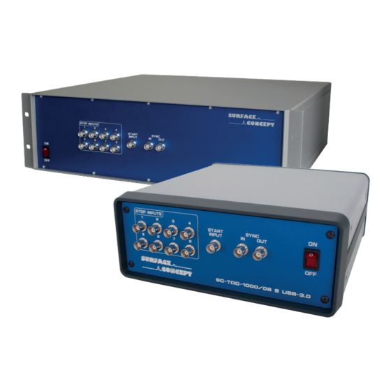
2. BNC Socket for Start Input (R012, 013 & 022), LEMO Socket for Start Input (R042) 3. BNC Sockets for Device Synchronization Signal IN and OUT 4. Power switch to turn the TDC ON/OFF. Lighted, when set to ON 5. Power Socket 6. USB Connection Socket SC-TDC-1000 S Series Manual | Surface Concept GmbH... -
Page 13: Tdc Stop Inputs
The maximum frequency of the start pulse must not exceed 7MHz. Do not forget to save the ini file after any changes you make and restart the software. For further information check the software manual. Note SC-TDC-1000 S Series Manual | Surface Concept GmbH... -
Page 14: Tdc Start Output (Sub-R 85 And E8 Only)
The TDC holds an internal electronics, which provide the TDC start signal for further extended measurement use. The “START OUT” (BNC socket) provides either the external start if applied or the internal start, generated by the FPGA. SC-TDC-1000 S Series Manual | Surface Concept GmbH... -
Page 15: Device Synchronization Signal In/Out
This leads to the multiple time histograms that appear sequentially in time. The multiple histograms can be resorted to one single time histogram by a MODULO-operation during data analysis. SC-TDC-1000 S Series Manual | Surface Concept GmbH... -
Page 16: Extended Measurement Range (Sub-R 85 And E8 Only)
In this case X can be set to -1. The reading of this entry is: “the reference of channel X is channel Y”. SC-TDC-1000 S Series Manual | Surface Concept GmbH... - Page 17 The default setting is 0 X = 0 switches off the sorting algorithm. The sorting algorithm works better at higher selected values, but higher values significantly increase the load on the PC CPU. SC-TDC-1000 S Series Manual | Surface Concept GmbH...
-
Page 18: Tag Signal Input (Sub-R E8 Only)
The number of bits which are available for each detector event (x, y, t) is defined by an additional parameter called “nBytes” in the tdc_gpx3.ini file. The corresponding entry in the tdc_gpx3.ini file is: nBytes = X The default setting is X is an integer value of either 4 or 8. SC-TDC-1000 S Series Manual | Surface Concept GmbH... -
Page 19: Master Reset Input (Sub-R E8 Only)
;must be set for using the state/sign input. Hereby the state/sign input functions in combination with the tag signal functioning as a timer, counting the internal 80MHz clock signal of the FPGA. A signal on “TAG IN“ resets the timer to 0. SC-TDC-1000 S Series Manual | Surface Concept GmbH... -
Page 20: Adc Input (Sub-R E8 Only)
In this case one has to use the positive input (“ADC IN +“) of the ADC, while terminating the negative input (“ADC IN -“) to ground. Please be aware that this way of operating is working, but it is more prone to noise. SC-TDC-1000 S Series Manual | Surface Concept GmbH... -
Page 21: Technical Data
(no calibration necessary) • Digital time bin resolution per channel: 82.3ps • 5.5ns pulse-pair resolution on one channel and 0ns between two channels SC-TDC-1000 S Series Manual | Surface Concept GmbH... - Page 22 32-fold multi-hit capability per channel • 40MHz internal device measurement rate • Stop Signal Input: Low voltage TTL on 50Ohm BNC socket • External Start Signal Input: Low voltage TTL on 50Ohm BNC socket SC-TDC-1000 S Series Manual | Surface Concept GmbH...
- Page 23 (no calibration necessary) • Digital time bin resolution per channel: 82.3ps • 5.5ns pulse-pair resolution on one channel and 0ns between two channels • Trigger to rising edge SC-TDC-1000 S Series Manual | Surface Concept GmbH...
- Page 24 External Start Signal Input: Low voltage TTL on 50Ohm BNC socket • External Start Signal Output: Low voltage TTL on 50Ohm BNC socket • Device Synchronization Signal Input: Low voltage TTL on 50Ohm BNC socket SC-TDC-1000 S Series Manual | Surface Concept GmbH...
- Page 25 Device Synchronization Signal Input: Low voltage TTL on 50Ohm BNC socket • USB Interface for Data Transfer Line Input Electrical Input (LINE) 85 V – 260 V, 50/60 Hz Power 65 Watt (max.) Fuse 1x T 1.6 A SC-TDC-1000 S Series Manual | Surface Concept GmbH...
- Page 26 SC-TDC-1000 S Series Manual | Surface Concept GmbH...
-
Page 27: List Of Figure
6 List of Figure Figure 1: General connection scheme of the SC-TDC-1000 S devices........................7 Figure 2: Schematic sketch of TDC functioning................................. 11 Figure 3a: Layout of the SC-TDC-1000/16S R042-10............................... 12 SC-TDC-1000 S Series Manual | Surface Concept GmbH... - Page 28 (Dr. Andreas Oelsner) This declaration does not represent a commitment to features or capabilities of the instrument. The safety notes and regulations given in the product related documentation must be observed at all times. SC-TDC-1000 S Series Manual | Surface Concept GmbH...
Need help?
Do you have a question about the SC-TDC-1000 S Series and is the answer not in the manual?
Questions and answers