Table of Contents
Advertisement
Quick Links
Advertisement
Table of Contents

Related Manuals for ISYGLT CC-03-SL-USB


Summary of Contents for ISYGLT CC-03-SL-USB
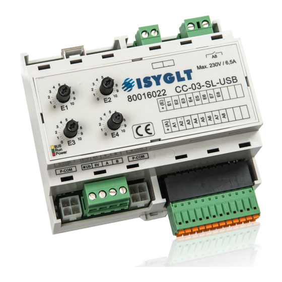
- Page 1 Technical Data / Instruction Manual CC-03-SL-USB Article no. 80016022 Compact Controller slim-line with USB interface Seebacher GmbH www.seebacher.de Phone: +49 (0) 80 41 / 77 77 6 Marktstrasse 57, 83646 Bad Tölz info@seebacher.de Fax: +49 (0) 80 41 / 77 77 2...
-
Page 2: Notes On Documentation
These instructions are intended for qualified personnel who are 1. Notes on documentation familiar with the assembly, installation and operation of the ISYGLT system. It is essential that you read these operating instructions through before commissioning and keep them accessible for further 1.1. -
Page 3: Safety Instructions
Protect module from humidity • and configuration of the ISYGLT module may only be carried out by trained staff. In addition to these safety instructions, you must also observe the special safety instructions listed in the individual chapters for Observe the electrical installation regulations of the country in which the individual acts. -
Page 4: Warranty
These are limited to the intended use of the module and refer EU on waste electrical and electronic equipment at the local collec- to the repair or replacement of the ISYGLT module. Please send the tion points for waste electrical and electronic equipment! device with an attached error description to our company address given below. -
Page 5: Product Description
• 1 USB Type-B interface for connection to the PC for programming Function displays • 1 flashing yellow LED „BUS“ indicates trouble-free data transfer on the ISYGLT BUS • 1 flashing green LED „Betrieb“ indicates the processor function: Steady flashing means „system ok, but no DCF-77 time detected“. -
Page 6: 10. Technical Data
24V DC 0V switching, against internal + limited to 150mA, max. cable length: 50m Relay output 230V 1500VA (max. 6.5A) with triac-zero-voltage switch Isolation voltage 1000V (ISYGLT BUS / analog outputs) Interface 1 RS-485 subnet BUS max. 5.6V limited by Z-diodes Interface 2 USB 2.0 Type-B socket to connect a PC for programming... - Page 7 Terminal Down right (front row) +(E) +24V current-limited for inputs Input 1 Input 2 Input 3 Input 4 Input 5 Input 6 Input 7 Input 8 Free Free Free Terminal Down right (back row) +(A) +24V current-limited for outputs Output 1 Output 2 Output 3 Output 4...
-
Page 8: 11. Wiring Diagram
11. Wiring diagram Misprints and technical changes reserved. Seebacher GmbH www.seebacher.de Phone: +49 (0) 80 41 / 77 77 6 Marktstrasse 57, 83646 Bad Tölz info@seebacher.de Fax: +49 (0) 80 41 / 77 77 2...
Need help?
Do you have a question about the CC-03-SL-USB and is the answer not in the manual?
Questions and answers