Advertisement
Quick Links
Series HKV-R Push'n'Go
Heizkreisverteiler mit Steckverbinder
Heating manifold with quick connection
Verwarmingscircuitverdeler met stekkerverbinding
Collecteur de chauffage avec fiche de connexion
Montage- und Betriebsanleitung
DE
Installation and operating manual
UK
Installatie- en bedieningshandleiding
NL
Notice d'installation et d'utilisation
FR
WattsWater.eu
Advertisement

Related Manuals for Watts HKV-R Push'n'Go Series


Summary of Contents for Watts HKV-R Push'n'Go Series
- Page 1 Series HKV-R Push'n'Go Heizkreisverteiler mit Steckverbinder Heating manifold with quick connection Verwarmingscircuitverdeler met stekkerverbinding Collecteur de chauffage avec fiche de connexion Montage- und Betriebsanleitung Installation and operating manual Installatie- en bedieningshandleiding Notice d’installation et d’utilisation WattsWater.eu...
- Page 2 MULTILINGUAL Inhalt Contents Allgemeine Informationen .........3 General information ...........3 1.1 Voraussetzungen ............3 1.1 Requirements ..............3 1.2 Produktkonformität ............3 1.2 Product conformity ............3 1.3 Produktbeschreibung .............3 1.3 Product description ............3 Sicherheit ..............4 Safety ................4 2.1 Darstellung von Sicherheitshinweisen ......4 2.1 Presentation of the safety information ......4 2.2 Bestimmungsgemäße Verwendung .......4 2.2 Intended use ..............4 2.3 Vorhersehbare Fehlanwendung ........4...
-
Page 3: Allgemeine Informationen
MULTILINGUAL 1 Allgemeine Informationen 1 General information 1.1 Voraussetzungen 1.1 Requirements Vor Beginn der Arbeiten muss der Installateur / Benutzer diese The installer or user must read, understand and observe this installa- Montage- und Betriebsanleitung lesen, verstehen und beachten. tion and operating manual before carrying out any operation. Die Heizkreisverteiler dürfen nur vom ausgebildeten Fach personal The heating manifold may only be fitted, adjusted and maintained by montiert, eingestellt und gewartet werden. - Page 4 MULTILINGUAL 2 Safety 2 Sicherheit 2.1 Darstellung von Sicherheitshinweisen 2.1 Presentation of the safety information ! WARNUNG Warnung vor möglichen schweren ! WARNING Warning of possible serious injury Verletzungen bei Nichtbeachtung des Hinweises. if the instruction is not followed. ...
-
Page 5: Technische Daten
MULTILINGUAL 3 Technische Daten Hydraulische Leistungsdaten max. Betriebsdruck 6 bar Mediumtemperatur 5… 55° C Medien Wasser/Wasser-Glykol-Gemische gemäß VDI 2035 Anschlüsse Primär Kreis & Endstückset G 1" Außengewinde Anzugsmomente 1" Verschraubungen 55 Nm PE-X Rohr gemäß DIN EN ISO 15875-2 oder PER-T Rohr Heizkreise Ø... -
Page 6: Technische Gegevens
MULTILINGUAL 3 Technische gegevens Hydraulische prestatiegegevens Max. werkdruk 6 bar Medium temperatuur 5… 55° C Media Water / water-glycolmengsels volgens VDI 2035 Aansluiting Primair circuit & eindstukset G 1" buitendraad Aanhalingen 1" schroefverbindingen 55 Nm PE-X-buis in overeenstemming met DIN EN ISO 15875-2 of PER-T-buis Ø... - Page 7 MULTILINGUAL 4 Diagramme 4 Diagrams 4 Diagrammen 4 Abaque Druckverlustdiagramm / Pressure loss diagram / Drukverliesdiagram / Courbe de perte de charge 1000 Abgänge / Outlets/ Départs / Uitstroom − 1000 10000 Volumenstrom / Flow rate / Débit / Debiet [l/h] Einstellung des Regulierventils / Adjustment of the control valves Instellen van de regelklep / Réglage de la vanne de régulation 1000...
- Page 8 MULTILINGUAL 5 Abmessungen 5 Overall dimensions 5 Afmetingen 5 Schémas d'encombrement M10x1 G3/4" Abgänge / Outlets / Départs / Uitstroom L1 = HKV-R 160,0 210,0 260,0 310,0 360,0 410,0 460,0 510,0 560,0 610,0 660,0 L2 = HKV-R + KFE90 (C) 209,5 259,5 309,5...
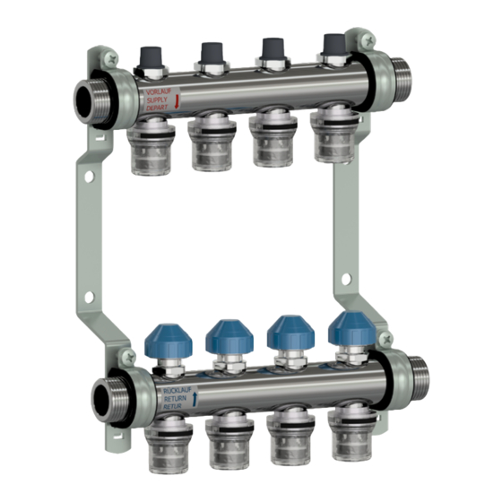
- Page 9 MULTILINGUAL 6 Komponentenübersicht 6 Components overview 6 Componentenoverzicht 6 Structure DE Bauteile EN Components Vorlauf Heizkreisverteiler 1 Manifold supply Rücklauf Heizkreisverteiler 2 Manifold return Regulier- und Absperrventil 3 Control and shut-off valve Absperrventil 4 Shut-off valve Steckverbindung Push'n'Go 5 Push'n'Go plug-in connection Wandhalter 6 Wall brackets Optionale Zubehörteile...
- Page 10 MULTILINGUAL 7 Montage und Inbetriebnahme 7 Installation and commissioning 7 Installatie en inbedrijfstelling 7 Installation et mise en service WARNUNG WARNING ! Heißes Wasser! ! Hot water! Greifen Sie während des Betriebes nicht an Verrohrungen Do not hold pipework or components while the unit is in und Bauteile.
- Page 11 MULTILINGUAL 7.2 Heizkreis Absperrung 7.2 Shutting off the heating circuit 7.2 Verwarmingscircuitvergrendeling 7.2 Fermeture des circuits de chauffage DE: Die Absperrventile im Rücklauf können, z.B. für das Spülen und Befüllen der Heizkreise, geschlossen werden. Dazu die Bauschutzkappe aufsetzen und Ventil rechtsdrehend schließen.
- Page 12 MULTILINGUAL • Verteiler mit Kugelhahn 1 und 2 absperren. • Close ball valves 1 and 2 on the manifold. • Alle Ventile im Rücklauf über die Bauschutzkappen schließen. • Close all valves on the return using the protective caps. • Spül- und Befüllschlauch am Vorlauf über KFE Hahn 3 •...
- Page 13 MULTILINGUAL 7.4 Einstellung des Volumenstroms 7.4 Adjusting the flow rate 7.4 Stroomaanpassing 7.4 Réglage du débit DE: Die Durchflussmenge wird an den Regulierventilen am Vorlauf eingestellt. Schutzkappe entfernen und Ventil durch Rechtsdrehen mit Entlüfterschlüssel schließen (= kleinster Wert). EN: The flow rate is set using the control valves on the supply side. Remove the protective cap and close the valve by turning the air vent key clockwise (= lowest value).
- Page 14 MULTILINGUAL 7.5 Demontage einer Steckverbindung 7.5 Plug-in connection disassembly 7.5 Demontage van een stekkerverbinding 7.5 Démontage d'une fiche de connexion HINWEIS Gebrauchte Push'n'Go Verbindungen nach NOTICE Ensure used Push'n'Go plug-in connections Demontage entsorgen. Gebrauchte Teile dürfen nicht mehr are disposed of after disassembly. Used parts may not be verwendet werden! Nur Originalteile verwenden! reused.
- Page 15 MULTILINGUAL 7.6 Montage einer Steckverbindung 7.6 Plug-in connection assembly 7.6 Montage van een stekkerverbinding 7.6 Montage d'une fiche de connexion DE: Das Ersatzteilset besteht aus Teilen 2-8. Den O-Ring (3) auf den Rand des Grundkörpers (1) aufschieben und Krone (4) auf den Grundkörper (1) aufdrücken. EN: The spare parts set consists of items 2-8.
- Page 16 Warranty: all sales and contracts for sale are expressly conditioned on the buyer’s assent to Watts terms and conditions found on its website at www.wattswater.eu/gtc/. Watts hereby objects to any term, different from or additional to Watts terms, contained in any buyer communication in any form, unless agreed to in a writing signed by an officer of Watts.
Need help?
Do you have a question about the HKV-R Push'n'Go Series and is the answer not in the manual?
Questions and answers