
Related Manuals for Watts Isotherm


Summary of Contents for Watts Isotherm
- Page 1 Isotherm Control station for constant maintenance of the supply temperature in surface heating systems Installation and Operating Manual (translated from the original operating manual) WattsWater.eu...
-
Page 2: Table Of Contents
Safety ............3 This installation and operating manual Presentation of safety information ......3 • is an integral part of the ISOTHERM Important safety information ........3 • contains instructions and information about safe and cor- Intended use .............. 3 rect installation and commissioning of the ISOTHERM Foreseeable misuse ........... -
Page 3: Safety
Operators are deemed to be qualified if they have read these operating instructions and understood the potential hazards • The ISOTHERM must not be used if it is damaged or is no longer operating correctly. In this case, contact your spe- associated with improper behavior. -
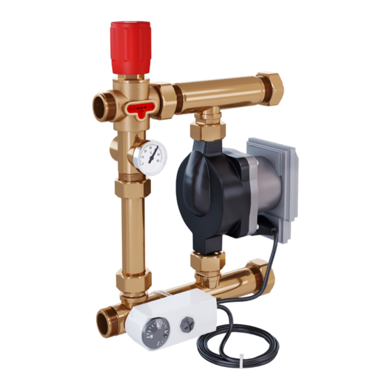
Page 4: Construction
55 °C 65 °C the temperature limiter: Primary supply (1" male thread) 1) There are two versions of Isotherm with 2 control ranges depending on the version Primary return (1" male thread) of the mixing valve. Connections to pipe network Surface heating/cooling supply (1" union nut) Primary (heat generator) 1"... -
Page 5: Overall Dimensions
6 Overall dimensions ca. 98 Fig. 6-1: Overall dimensions 7 Pressure loss diagram 1.000 : Bypass : Einspritzung / Injection : Verteilerseitig / Manifold side 1.000 10.000 Flow rate [l/h] Fig. 7-1: Pressure loss diagram ISOTHERM-IM-DE-W-UK-01-2021-Rev0 | Part no. 10019091... -
Page 6: Installation And Commissioning
The installation and commissioning of • The cables must not be under tension. the ISOTHERM must be carried out only by trained per- sonnel who have been authorized by the manufacturer. 4. Set the target supply temperature on the setting hand wheel. -
Page 7: Temperature Limiter
Fig. 8-6: Increase of the target supply temperature The set temperature range is between 30 and 50 °C or 45 and 60 °C according to the version of ISOTHERM. However, the setting hand wheel can be turned fur- ther in both directions. This causes only small chang- es of the target temperature outside of the tempera- ture range. -
Page 8: Troubleshooting
With installation of a control station ISOTHERM into a heating system with boilers with small water volumes, with combined radiator and surface heating systems or with plants with warm water priority function the installation of a hydraulic separator between boiler and heating circuit is recommended, in order to disconnect the heating circuits hydraulically from the boiler. -
Page 9: Maintenance
Wear 10.2 Replacement of wear parts heat-resistant safety gloves if it is necessary to carry out Please note that the ISOTHERM contains parts that, for tech- work on hot components. nical reasons, are subject to wear depending on the intensity... -
Page 10: Disposal
Inform the manufacturer of decommissioning and disposal of the ISOTHERMfor statistical purposes. Die im vorliegenden Produktdatenblatt enthaltenen Beschreibungen und Bilder dienen ausschließlich zu Informationszwecken und sind ohne Gewähr. Watts Industries behält sich das Recht auf technische und konstruktive Änderungen an seinen Produkten ohne vorherige Ankündigung vor.
Need help?
Do you have a question about the Isotherm and is the answer not in the manual?
Questions and answers