Table of Contents
Advertisement
Available languages
Available languages
Quick Links
Operating Instructions & Parts Manual
Please read and save these instructions. Read carefully before attempting to assemble,
install, operate or maintain the product described. Protect yourself and others by
observing all safety information. Failure to comply with instructions could result in per-
sonal injury and/or property damage! Retain instructions for future reference.
BUILT TO LAST
See Warranty on page 17 for important information about
commercial use of this product.
Specifications
Motor . . . . . . . 1/4 HP, 120 Volt, 5 Amp
Delivery . . . . . . . 0.2 gallon per minute
Max. Pressure . . . . . . . . . . . . . . 2500 psi
Refer to product decal for exact
specifications.
FOR HOUSEHOLD USE ONLY
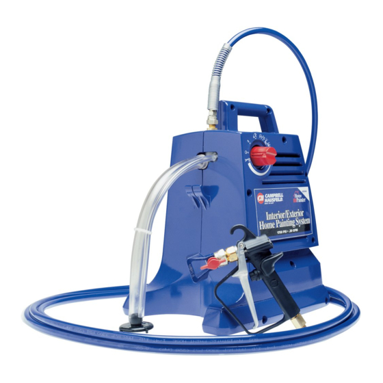
Description
Airless paint sprayers are capable of
spraying a variety of latex and oil-
based paints, as well as stains, preserv-
atives and other non-abrasive finishes.
The coatings that can be sprayed will
vary depending on the sprayer.
Unpacking
After unpacking the unit, inspect care-
fully for any damage that may have
occurred during transit. Make sure to
tighten all connection points before
putting into service. There will be
some lubricant in the sprayer head
from the testing process. Spray a short
burst onto a practice surface after fill-
ing the canister with paint. This will
clear the lubricant without affecting
the paint job or the coating.
REMINDER: Keep your dated proof of purchase for warranty purposes!
Attach it to this manual or file it for safekeeping.
© 2004 Campbell Hausfeld/
Scott Fetzer
The
HousePainter
General Safety
This manual contains information that
is very important to know and under-
stand. This information is provided for
SAFETY and to PREVENT EQUIPMENT
PROBLEMS. To help recognize this
information, observe the following
symbols.
DANGER
!
hazardous situation which, if not
avoided, WILL result in death or seri-
ous injury.
WARNING
!
ardous situation which, if not avoided,
COULD result in death or serious injury.
For parts, product & service information
visit www.chpower.com
EZ5000 Series
®
Danger indicates
an imminently
Warning indicates
a potentially haz-
IN423200AV 3/04
Advertisement
Table of Contents

Related Manuals for Campbell Hausfeld HousePainter EZ5000 Series


Summary of Contents for Campbell Hausfeld HousePainter EZ5000 Series
-
Page 1: Specifications
REMINDER: Keep your dated proof of purchase for warranty purposes! Attach it to this manual or file it for safekeeping. For parts, product & service information © 2004 Campbell Hausfeld/ Scott Fetzer EZ5000 Series HousePainter... -
Page 2: General Safety
Operating Instructions & Parts Manual General Safety (Cont.) Caution indicates CAUTION a potentially haz- ardous situation which, if not avoided, MAY result in minor or moderate injury. Notice indicates NOTICE important infor- mation that, if not followed, may cause damage to the equipment. IMPORTANT SAFETY INSTRUCTIONS SAVE THESE INSTRUCTIONS –... - Page 3 Use only conductive or grounded high-pressure airless paint sprayer hoses specified by the manufacturer. • Verify that all containers and col- lection systems are grounded to prevent static discharge.
- Page 4 Operating Instructions & Parts Manual General Safety (Cont.) To reduce the risk WARNING of skin injection: • Do not aim the gun at or spray any person or animal. • Keep hands and other body parts away from the discharge. Do not try to stop leaks with any part of the body.
-
Page 5: Tools Required
General Safety (Cont.) Q turn the unit to the Prime position (see Figure 5) ...OR ... Q turn the unit to the Off posi- tion (see Figure 6). Figure 6 - Icon Figure 5 - Icon showing Off showing Prime position position Be thoroughly familiar with the... - Page 6 Operating Instructions & Parts Manual Set-Up (Cont.) cleans up with something other than water), you should flush the system with the cleaning fluid rec- ommended by the coating manufac- turer. To flush the system, follow the instructions for priming – see Page 8.
- Page 7 Set-Up (Cont.) To extend your reach for floors and ceilings, consider using the 24” Spray Wand accessory, which attach- es between the gun and tip. For floors, it angles the tip away from your feet, while allowing a comfort- able spraying position for your arm and back.
- Page 8 Operating Instructions & Parts Manual Step 1 – Priming (Cont.) Control to the Prime position (see Figure 14). After a few seconds, the coating will come up the suction tube and then out the bypass tube. Figure 14 - Icon Initially, there will showing Prime be air bubbles in...
- Page 9 Step 2 – Using Your HousePainter (Cont.) much as possible. If you still have ‘tails’ at the highest pressure setting, or if you have any other pattern prob- lems, please see the suggestions in the Troubleshooting chart beginning on page 13. 12”...
-
Page 10: Step 3 - Cleaning & Storage
Operating Instructions & Parts Manual Step 2 – Using Your HousePainter (Cont.) roller with paint. When paint begins to dot the roller cover (see Figure 19) continue to hold the trigger and begin rolling the wall . When the roller cover is saturated, release the trigger and continue rolling the surface. - Page 11 Step 3 – Cleaning & Storage (Cont.) changing buckets. When you are sure that the pump is clean, get one more bucket of water. Place the suction tube in it and turn the One Touch Control knob to the clean hose position (see Figure 22).
-
Page 12: Maintenance Chart
Operating Instructions & Parts Manual Maintenance Chart Maintenance Item Check Product safety Before each use labels Trigger adjust- Before each use ment Airless hose Before each use Suction tube Before each use Bypass tube Before each use Suction filter Before each use and every 5 gal. -
Page 13: Troubleshooting Chart
Troubleshooting Chart Symptom Possible Cause(s) Motor runs but won't 1. Inlet or outlet valve stuck. prime material 2. Suction tube connection loose. 3. Control lever in spray or roll posi- tion. 4. Air in hydraulic system causing loss of suction and no diaphragm movement. - Page 14 Operating Instructions & Parts Manual Troubleshooting Chart (Cont.) Symptom Possible Cause(s) Sprayer motor doesn’t 1. Paint system is under pressure or start or just hums control is in spray or roll posi- tion. 2. Motor thermal overload switch is tripped. 3.
- Page 15 Troubleshooting Chart (Cont.) Symptom Possible Cause(s) Poor spray pattern – 1. Material too thick or not tails, bursts of material, strained. splotches in pattern 2. Spray tip dirty, worn or defective. 3. Dirty or worn inlet or outlet valve. 4. Pressure is adjusted too low for material being sprayed.
- Page 16 EZ500430SV Suction bell and filter Outlet valve 25’ Hose (not included) See product insert for spray tips and accessories www.chpower.com Address parts correspondence Campbell Hausfeld 100 Production Drive Harrison, OH 45030 U.S.A. Part Number AL005102SV EZ500220SV MP217600AJ...
- Page 17 8. RESPONSIBILITIES OF PURCHASER UNDER THIS WARRANTY: A. Provide dated proof of purchase and maintenance records. B. Deliver or ship the Campbell Hausfeld product or component to the nearest Campbell Hausfeld Authorized Service Center. Freight costs, if any, must be borne by the purchas- C.
-
Page 19: Spécifications
MÉMENTO: Gardez votre preuve datée d'achat à fin de la garantie! Joignez-la à ce manuel ou classez-la dans un dossier pour plus de sécurité. © 2004 Campbell Hausfeld/ Scott Fetzer Série EZ5000 HousePainter Sécurité... -
Page 20: Instructions De Mise À Terre
Manuel de pièces et instructions de fonctionnement ATTENTION Attention indique une situation poten- tiellement dangereuse qui, si elle n’est pas évitée, POURRAIT risquer d’entraîn- er des lésions corporelles mineures ou modérées. AVIS Avis indique de l’information impor- tante qui pourrait endommager l’équipement si elle n’est pas respectée. - Page 21 Sécurité générale (suite) longe n’est pas endommagée. En util- isant une rallonge, s’assurer d’en utilis- er une suffisamment lourde pour trans- porter le courant que votre produit débite. Un cordon sousdimensionné provoquera une chute de tension de ligne menant à une perte de courant et à...
- Page 22 Manuel de pièces et instructions de fonctionnement Sécurité générale (suite) corps loin de la décharge. Ne pas essayer d’arrêter les fuites avec toute part du corps. • Toujours utiliser un embout pro- tecteur de la buse. Ne pas pulvériser sans avoir l’embout protecteur de buse en place.
-
Page 23: Installation
Sécurité générale (suite) Figure 6 - Icône Figure 5 - Icône montrant la montrant la position “Off” position (Arrêt). d’amorçage. Il faut aussi connaître les commandes. AVERTISSEMENT Pour réduire les risques de blessures : • Toujours porter des gants appro- priés, une protection pour les yeux et un respirateur ou un masque pen- dant la peinture. - Page 24 Manuel de pièces et instructions de fonctionnement er le système suivre les instructions d’amorce - voir la page 8. Laisser le pulvérisateur fonctionner à la position d’amorce jusqu’à ce qu’un fluide de nettoyage clair sorte par le tube de dérivation. Suivre aussi cette procédure après que l’appareil ait été...
- Page 25 Installation (suite) vérisation directement au-dessus de la tête et donne un autre 2 pieds élimi- nant ainsi le besoin d’une échelle. Quelques autres mots sur les murs Si l’on n’est pas confortable pour pul- vériser les murs intérieurs, considérer utiliser l’accessoire à rouleau. Pour utiliser cet accessoire, retirer la buse de pulvérisation du pistolet et fixer le rouleau (voir la figure 10).
- Page 26 Manuel de pièces et instructions de fonctionnement Étape 1 - Amorçage (suite) Si l’on éprouve des difficultés d’amorçage, voir les suggestions sous le tableau de dépan- nage commençant à la page 13. Figure 14 - Icône montrant la position d’amorçage Figure 15 - Icône montrant la posi- tion de pulvérisation Étape 2 - Utiliser...
- Page 27 Étape 2 - Utiliser votre HousePainter (suite) Pulvériser Se placer pour que la buse de pulvérisa- tion soit de 25 à 30 cm (10-12 po) de la 12 po Tenir le pistolet de pulvérisation Couche Couche Couche lourde mince mince Surpulvérisation Surpulvérisation Résultat de la flexion du poignet...
-
Page 28: Étape 3 - Nettoyage Et Rangement
Manuel de pièces et instructions de fonctionnement Étape 2 - Utiliser votre HousePainter (suite) à rouler la surface. Désengager la gâchette seulement lorsque l’en- veloppe du rouleau a besoin de plus de peinture. Avec ce système on économique envi- ron 1/3 de la quantité de peinture util- isée pour le rouleau manuel. - Page 29 Étape 3 – Nettoyage et rangement (suite) mande à touche unique à la position du nettoyage de tuyau (voir la fig- ure 22). Tourner la buse réversible du pistolet à la position de nettoyage. Pulvériser dans un seau de déchets jusqu’à...
- Page 30 Manuel de pièces et instructions de fonctionnement Tableau d’entretien Entretien Article Vérification Étiquettes de Avant chaque sécurité du utilisation produit Ajustement de Avant chaque la gâchette utilisation Tuyau sans air Avant chaque utilisation Tube d’aspira- Avant chaque tion utilisation Tube de déri- Avant chaque vation utilisation...
- Page 31 Tableau de dépannage Symptôme Causes possibles Moteur tourne 1. Soupape d’entrée ou de sortie mais n’amorce pas coincée le matériau 2. Connexion du tube d’aspiration desserré 3. Levier de commande en posi- tion de pulvérisation ou du rouleau 4. De l’air dans le système hydraulique provoquant une perte d’aspiration et aucun déplacement du diaphragme.
- Page 32 Manuel de pièces et instructions de fonctionnement Tableau de dépannage (suite) Symptôme Causes possibles Le pistolet continue 1. L’accumulation de peinture à à pulvériser lorsque l’intérieur de la soupape du pis- la gâchette est tolet ou la soupape du pistolet dégagée.
- Page 33 Tableau de dépannage (suite) Symptôme Causes possibles Fuites d’huile ou 1. *Fuite d’huile entre le bloc huile dans la pein- et le boîtier hydraulique. ture. 2. * Fuite d’huile du moteur, sceau du moteur défectueux. 3. * Égratignure profonde dans les rainures par le diaphragme.
- Page 34 Manuel de pièces et instructions de fonctionnement Tableau de dépannage (suite) Symptôme Causes possibles 6. Filtre du pistolet bloqué. 7. Buse est trop large pour le matériau à pulvériser. 8. Buse de pulvérisation en position de nettoyage. Pour libérer une aspiration coincée Utiliser soit un tournevis ou votre doigt, pousser à...
- Page 35 Tuyau de 25 pi (non inclus) Voir la documentation du produit pour les buses de pulvérisation et les accessoires Adressez la correspondance au sujet des pièces à : Campbell Hausfeld 100 Production Drive Harrison, OH 45030 U.S.A. Numéro de pièce EZ500420SV...
- Page 36 8. RESPONSABILITÉS DE L’ACHETEUR AUX TERMES DE CETTE GARANTIE: A. Fournir une preuve d’achat datée et un état d’entretien. B. Livraison ou expédition du produit ou de la pièce Campbell Hausfeld au Centre De Service Autorisé Campbell Hausfeld. Taux de frais, si applicables, sont la responsabilité de l’a- cheteur.
Need help?
Do you have a question about the HousePainter EZ5000 Series and is the answer not in the manual?
Questions and answers