Greystone Energy Systems CR3 Series Installation Instructions Manual
Cleanroom monitor
Hide thumbs
Also See for CR3 Series:
- Installation instructions manual (12 pages) ,
- Installation instructions manual (12 pages) ,
- Installation instructions manual (12 pages)
Table of Contents
Advertisement
Quick Links
BEFORE INSTALLATION
Read these instructions carefully before installing and commissioning the cleanroom monitor. Failure
to follow these instructions may result in product damage. Do not use in an explosive or hazardous
environment, with combustible or flammable gases, as a safety or emergency stop device or in any
other application where failure of the product could result in personal injury. Take electrostatic discharge
precautions during installation and do not exceed the device ratings.
MOUNTING
STEP 1 - As illustrated in Figure 1, unscrew four screws
from faceplate, set screws aside, and remove faceplate
from mounting bracket.
Cut hole in wall 210 mm x 167 mm
high. Ensure unit can be secured to
wall stud or equivalent on at least
two sides.
STEP 2 - As illustrated in Figure 2, feed wires through
mounting bracket and conduit connector/cable gland and
secure.
STEP3 - As illustrated in Figure 3, insert mounting bracket
into hole in wall.
Figure 2
Figure 2
IN-CR3BXXNET-01
04/20
Copyright © Greystone Energy Systems, Inc. All Rights Reserved Phone: +1 506 853 3057 Web: www.greystoneenergy.com
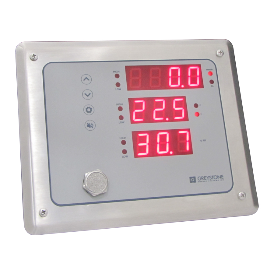
INTRODUCTION
The CR3 Series Cleanroom Monitor was developed specifically
to allow for monitoring of confined spaces with accuracy and
reliability.
The CR3B features remote mounted sensors for monitoring
temperature, humidity and pressure in an adjacent space from
where the main panel is mounted in. The CR3B is available with
output signal of either Analog, BACnet ® or Modbus. Standard
features include adjustable alarm relays for each parameter,
audible/visual alarms, and large LED displays.
The CR3B main panel and remote sensor module are housed in
flush fitting stainless-steel plates that enables the user to wipe
down the units when necessary.
210 mm
CLEANROOM MONITOR
CR3B Network - Installation Instructions
Figure 1
Figure 1
Figure 3
Figure 3
Page 1
Advertisement
Table of Contents

Related Manuals for Greystone Energy Systems CR3 Series


Summary of Contents for Greystone Energy Systems CR3 Series
- Page 1 STEP3 - As illustrated in Figure 3, insert mounting bracket into hole in wall. Figure 2 Figure 2 Figure 3 Figure 3 IN-CR3BXXNET-01 04/20 Copyright © Greystone Energy Systems, Inc. All Rights Reserved Phone: +1 506 853 3057 Web: www.greystoneenergy.com Page 1...
- Page 2 For end of Line (EOL) device place termination resister jumper in ON position, for all other devices, place jumper in OFF position. Page 2 IN-CR3BXXNET-01 04/20 Copyright © Greystone Energy Systems, Inc. All Rights Reserved Phone: +1 506 853 3057 Web: www.greystoneenergy.com...
- Page 3 Connect Shield One End Only CONNECTORS (Front view, screw on top) Figure 12 ALARM CONTACTS ANALOG OUTPUTS COMMS DIG IN Page 3 IN-CR3BXXNET-01 04/20 Copyright © Greystone Energy Systems, Inc. All Rights Reserved Phone: +1 506 853 3057 Web: www.greystoneenergy.com...
-
Page 4: Alarm Relays
If the alarm condition is reset and then set again, the buzzer will activate again. The buzzer provides a “beeping” or “chirping” sound, not a continuous tone. Page 4 IN-CR3BXXNET-01 04/20 Copyright © Greystone Energy Systems, Inc. All Rights Reserved Phone: +1 506 853 3057 Web: www.greystoneenergy.com... -
Page 5: Digital Input
Installer Menu items such as TEMP DISPLAY. Display brightness may be changed from high to low using DISPLAY BRIGHTNESS via the User Menu. Page 5 IN-CR3BXXNET-01 04/20 Copyright © Greystone Energy Systems, Inc. All Rights Reserved Phone: +1 506 853 3057 Web: www.greystoneenergy.com... -
Page 6: Operation
2. Address 0-127 for BACnet® Addr b a c 1-255 for Modbus 0 to 255 0 0 3 Page 6 IN-CR3BXXNET-01 04/20 Copyright © Greystone Energy Systems, Inc. All Rights Reserved Phone: +1 506 853 3057 Web: www.greystoneenergy.com... - Page 7 10. AO RH Override 0 to 100 (Default = 0) 11. AO DP Override a o 3 0 to 100 (Default = 0) Page 7 IN-CR3BXXNET-01 04/20 Copyright © Greystone Energy Systems, Inc. All Rights Reserved Phone: +1 506 853 3057 Web: www.greystoneenergy.com...
- Page 8 7. RH Alarm High Setpoint (Resolution is 1 %RH via the menu) r h s p 40 to 90% RH Page 8 IN-CR3BXXNET-01 04/20 Copyright © Greystone Energy Systems, Inc. All Rights Reserved Phone: +1 506 853 3057 Web: www.greystoneenergy.com...
- Page 9 Note that the setpoint resolution is limited when setting with the menu, but higher resolution is available via the network. Page 9 IN-CR3BXXNET-01 04/20 Copyright © Greystone Energy Systems, Inc. All Rights Reserved Phone: +1 506 853 3057 Web: www.greystoneenergy.com...
-
Page 10: Specifications
70mm 2.76“ 36mm 225 mm 1.46“ 8.86“ 82.6 mm 115mm 3.25“ 4.53“ 35mm 1.38“ 182.5 mm 7.19“ 20 mm 0.79“ Page 10 IN-CR3BXXNET-01 04/20 Copyright © Greystone Energy Systems, Inc. All Rights Reserved Phone: +1 506 853 3057 Web: www.greystoneenergy.com... -
Page 11: Bacnet® Protocol
BACnet® and Modbus setup guide downloads are available online. BACNET® PROTOCOL http://downloads.greystoneenergy.com/SG/SG-CR3-Bacnet-01.pdf MODBUS PROTOCOL http://downloads.greystoneenergy.com/SG/SG-CR3-Modbus-01.pdf Page 11 IN-CR3BXXNET-01 04/20 Copyright © Greystone Energy Systems, Inc. All Rights Reserved Phone: +1 506 853 3057 Web: www.greystoneenergy.com... - Page 12 Page 12 IN-CR3BXXNET-01 04/20 Copyright © Greystone Energy Systems, Inc. All Rights Reserved Phone: +1 506 853 3057 Web: www.greystoneenergy.com...
Need help?
Do you have a question about the CR3 Series and is the answer not in the manual?
Questions and answers