Table of Contents
Advertisement
Quick Links
ADXD-LPR User Manual
ADXD-H-NMS-AC
ADXD-H-POI-X
LAN0
HOST
REMOTE
LAN0
LAN1
LINK
SERVICE
BATTERY
BTS
DL/UL
OFF - AC - ON
AC IN 110V
Advanced RF Technologies, Inc.
Version 0.1
ADXD-H-POI-X
ADXD-H-POI-X
ADXD-H-POI-X
ADXD-H-POI-X
BTS
BTS
DL/UL
DL/UL
BTS
BTS
DL/UL
DL/UL
3116 West Vanowen St.
Burbank, CA 91505
Tel: 818-840-8131
Fax: 818-840-8138
www.adrftech.com
ADXD-H-ODU
i
Advertisement
Table of Contents

Related Manuals for ADRF ADXD-LPR


Summary of Contents for ADRF ADXD-LPR
- Page 1 ADXD-LPR User Manual Version 0.1 ADXD-H-NMS-AC ADXD-H-POI-X ADXD-H-POI-X ADXD-H-POI-X ADXD-H-POI-X ADXD-H-POI-X ADXD-H-ODU LAN0 HOST REMOTE DL/UL DL/UL LAN0 LAN1 LINK SERVICE BATTERY DL/UL DL/UL DL/UL OFF - AC - ON AC IN 110V 3116 West Vanowen St. Burbank, CA 91505...
- Page 2 Information in this document is subject to change without notice. Advanced RF Technologies, Inc. 1996-2019. All rights reserved. Please send comments to: E-Mail: info@adrftech.com Phone: (818) 840-8131 (800) 313-9345 Fax: (818) 840-8138 Address: Advanced RF Technologies, Inc. Attention: Technical Publications Department 3116 Vanowen St.
- Page 3 Revision History Version Author Descriptions Date YH Ko Draft 20/04/03 Change List Version Change list Contents Advanced RF Technologies, Inc.
-
Page 4: Table Of Contents
Table of Contents Introduction ..............................10 Highlights ..............................10 ADXD LPR Quick View ..........................11 1.2.1 HE Quick View ............................ 11 1.2.2 LPR Quick View ........................... 11 1.2.3 LPR HUB Quick View ........................... 12 Warnings and Hazards ..........................12 Block Diagram ..............................16 ADXD LPR Block Diagram ........................... - Page 5 5.2.1 HE Installation Procedure ........................30 5.2.1.1 Installing a ADXD DAS HE in a rack ................... 30 5.2.2 LPR Installation Procedure (Wall mount) ................... 32 5.2.3 RF coaxial cable and antenna connection ..................33 Grounding ..............................33 Optic Port Cleaning ............................ 34 Web-GUI ................................
- Page 6 6.2.7 Logout ..............................52 Guest Mode ............................... 52 System-Wide Specifications ..........................53 Mechanical Drawings ............................55 HE ................................55 LPR ................................56 Advanced RF Technologies, Inc.
- Page 7 ADXD-H-ODU LED ..........................24 Figure 3-11 ODU RF Ports ............................24 Figure 3-12 ODU Optic Ports..........................24 Figure 3-13 ADXD-LPR Bottom and Side View ....................... 25 Figure 3-14 LPR Connection Diagram ........................26 Figure 3-15 LPR Ports and Switches ........................26 Figure 4-1 HE Rack Mount (Front &...
- Page 8 Tables Table 2-1 ADXD LPR Scalability ........................... 17 Table 3-1 NMS LED Specifications ........................19 Table 3-2 POI LED Specifications ........................23 Table 3-3 POI RF port ............................23 Table 3-4 ODU LED Specifications ........................24 Table 6-1 Account Information for Login ......................34 Table 6-2 Navigation tree ...........................
- Page 9 The following is a list of abbreviations and terms used throughout this document. Abbreviation/Term Definition Automatic Gain Control Automatic Level Control AROMS ADRF’ Repeater Operation and Management System Band Combiner Unit Base Transceiver Station CDMA Code Division Multiple Access Channel combiner...
-
Page 10: Introduction
1. INTRODUCTION Currently the ADXD supports 600MHz, 700 MHz (Lower A, Lower B, Lower C and Upper C), SMR800/Cellular, PCS, AWS, WCS, BRS, CBRS band 1.1 Highlights Modular Structure (HE) Supports multi bands service in one body Supports up to 12 slot available for POI, ODU, etc. ... -
Page 11: Adxd Lpr Quick View
AUX 5 AUX 5 AUX 7 AUX 7 Fan Unit Figure 2-1 ADXD HE Quick View (Front and Rear) 1.2.2 LPR Quick View Internal Antenna ADXD-LPR-S1 OPTIC B / H SERVICE -57V IN MAIN DAISY DAISY MAIN ON/OFF +12V DC IN... -
Page 12: Lpr Hub Quick View
Figure 2-3 ADXD LPR HUB Quick View 1.3 Warnings and Hazards WARNING! ELECTRIC SHOCK Opening the ADXD-LPR could result in electric shock and may cause severe injury. WARNING! EXPOSURE TO RF FCC RF Radiation Exposure Statement: This equipment complies with FCC RF radiation exposure limits set forth for an uncontrolled environment. - Page 13 WARRANTY Opening or tampering the ADXD DAS will void all warranties. Lithium Battery: CAUTION. RISK OF EXPLOSION IF BATTERY IS REPLACED BY INCORRECT TYPE. DISPOSE OF USED BATTERIES ACCORDING TO INSTRUCTIONS. Ethernet Instructions: This equipment is for indoor use only. All cabling should be limited to inside the building.
- Page 14 Laser Safety Fiber optic ports of the ADXD LPR emit invisible laser radiation at the 1270, 1330nm wavelength window. To avoid eye injury never look directly into the optical ports, patch cords or optical cables. Do not stare into beam or view directly with optical instruments. Always assume optical output is on. Only technicians familiar with fiber optic safety practices and procedures should perform optical fiber connections and disconnections of the ADXD DAS and the associated cables.
- Page 15 RSS-GEN, Sec. 7.1.2– (transmitters) Under Industry Canada regulations, this radio transmitter may only operate using an antenna of a type and maximum (or lesser) gain approved for the transmitter by Industry Canada. To reduce potential radio interference to other users, the antenna type and its gain should be so chosen that the equivalent isotropically radiated power (e.i.r.p.) is not more than that necessary for successful communication.
-
Page 16: Block Diagram
2. BLOCK DIAGRAM 2.1 ADXD LPR Block Diagram UL IN DL/UL CBRS UL IN DL/UL CBRS DL CBRS CBRS UL CBRS DL UL IN DL/UL OPTIC CBRS UL ANT1 BRS DL BRS DL BRS UL LPR RF BRS UL AWS DL UL IN DL/UL PCS/AWS DL... -
Page 17: Adxd Lpr Scalability
2.2 ADXD LPR Scalability Table 2-1 ADXD LPR Scalability Unit Scalability Remarks Supported band 700F, Cellular, SMR800, PCS, AWS, BRS, CBRS No limitation in 12 slots except NMS No limitation through NMS daisy chain link (1 per one HE 19” Rack) No limitation in 12 slots except NMS In case of Aux, No limit in 8 Aux ports No limitation through Optic daisy chain link... -
Page 18: Adxd Lpr Overview
3. ADXD LPR OVERVIEW 3.1 Head End The head end unit always has to be connected to the Base Station using a direct cabled connection. This system has not been approved for use with a wireless connection via server antenna to the base station. ... -
Page 19: Nms (Network Management System)
3.1.1 NMS (Network Management System) Functions and features Supports SNMP v1, v2, and v3 (get, set & trap) and web-based GUI Interface. Monitors alarms and status Provides control interfaces with all subordinate modules Provides overall DAS structure via the auto tree update function ADXD-H-NMS-AC is for AC type ADXD-H-NMS-DC is for DC type HE’s battery backup option is available only in ADXD-H-NMS-AC... -
Page 20: Ethernet Port
3.1.1.2 Ethernet Port The Ethernet port can be used to communicate directly with the ADXD DAS using a RJ-45 crossover cable or can also be used to connect the ADXD DAS to an external modem box. LAN0 LAN1 Figure 3-4 Ethernet Port 3.1.1.3 Host/Remote Switch The Host/Remote Switch allows the user to switch the default Repeater IP, Subnet Mask, and Gateway of... -
Page 21: Poi (Adxd-H-Poi-X)
LAN1 SERVICE LINK BATTERY OFF - AC - ON AC IN 110V 3.1.1.5 POI (ADXD-H-POI-x) ADXD-H-POI-X DL/UL Figure 3-6 POI front View Functions and features Provide RF interface with BTS Each POI has independent gain control and filtering Modular type and hot swappable Supports duplex port and simplex RX port Easily support additional frequency bands by adding a POI Reduces complexity and overall equipment size... -
Page 22: Figure 3-7 Poil Front View
ADXD-H-POIL-X Figure 3-7 POIL front View Functions and features Provide RF interface with BTS Each POIL has independent gain control and filtering Modular type and hot swappable Supports duplex port and simplex RX port Easily support additional frequency bands by adding a POIL Reduces complexity and overall equipment size ... -
Page 23: Led
3.1.2.1 LED POI has LEDs on the front panel as shown in Figure 3-8. Figure 3-8 POI LED Table 3-2 POI LED Specifications Specifications Power Solid Green POI power is ON and POI/POIL is normal status Solid Red POI power is ON and POI/POIL is hard fail alarm status Solid Yellow POI power is ON and POI/POIL is soft fail alarm status 3.1.2.2 RF Ports... -
Page 24: Led
Figure 3-9 ADXD-H-ODU Front view Functions & Features Converts signal from RF to digital optic and transports signals up to a maximum of 20Km. One ADXD-H-ODU supports up to 8 bands Has 4 SFP+ ports for RU connections. Spec Size: 2.62 x 17.0 x 6.86 (in) Weight: 5.6lbs 3.1.3.1 LED... -
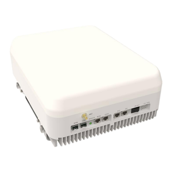
Page 25: Lpr (Low Power Ru)
Power Input: -12 or -48VDC (In case of Optic link), PoE(In case of Ethernet link) ADXD-LPR-S1 OPTIC B / H SERVICE -57V IN MAIN DAISY DAISY MAIN ON/OFF +12V DC IN Figure 3-13 ADXD-LPR Bottom and Side View Advanced RF Technologies, Inc. -
Page 26: Lpr Connection
3.2.1.1 LPR Connection ETHERNET ADXD-LPR-BE PoE(-57V) (LPR HUB) SERVICE D-SFP M-SFP SERVICE SERVICE from-M to-D ALARM ALARM OFF - AC - ON OFF - AC - ON AC IN AC IN ETHERNET PoE(-57V) OPTIC ADXD-LPR-BE-PSUA ADXD-LPR-BE-PSUA ADXD-LPR-BE SERVICE D-SFP M-SFP... -
Page 27: Led (Service)
ALARM OFF - AC - ON OFF - AC - ON AC IN AC IN ADXD-LPR-BE-PSUA ADXD-LPR-BE-PSUA ADXD-LPR-BE Power Input: 110VAC Chassis: 5.83 x 14.34 x 6.86 in (148 x 364 x 174 mm) Ethernet Hub: 1.9 x 13.44 x 5.91 in (48 x341x 150 mm) Hub PSU: 1.9 x 13.44 x 5.91 in (48 x341x 150 mm) -
Page 28: Figure 4-1 He Rack Mount (Front & Rear View)
ADXD-H-NMS-AC ADXD-H-POI-X ADXD-H-POI-X ADXD-H-POI-X ADXD-H-POI-X ADXD-H-POI-X ADXD-H-ODU LAN0 HOST REMOTE DL/UL DL/UL LAN0 AUX 1 AUX 1 LAN1 AUX 3 AUX 3 LINK SERVICE BATTERY AUX 5 AUX 5 DL/UL DL/UL DL/UL OFF - AC - ON AUX 7 AUX 7 AC IN 110V Figure 4-1 HE Rack Mount (Front &... -
Page 29: Lpr
4.2 LPR 4.2.1 Wall Mount Wall Figure 4-2 LPR Wall Mount Advanced RF Technologies, Inc. -
Page 30: Installation
Open and check each package against the packing list. If any items are missing, contact ADRF customer service. -
Page 31: Figure 5-1 He Installation Procedure
Figure 5-1 HE Installation Procedure Advanced RF Technologies, Inc. -
Page 32: Lpr Installation Procedure (Wall Mount)
> Place the ADXD-LPR mounting template up against the wall and mark of mount holes > Mount the ADXD-LPR to wall use the four mounting holes on the wall mount bracket > Connect the GND cable ... -
Page 33: Rf Coaxial Cable And Antenna Connection
AUX 3 Ground Terminal AUX 5 AUX 5 AUX 7 AUX 7 Fan Unit Figure 5-3 HE Ground Cable Connection, Protective Earthing Conductor (HE chassis rear side) ADXD-LPR-S1 OPTIC B / H -57V IN MAIN DAISY DAISY MAIN ON/OFF +12V DC IN... -
Page 34: Optic Port Cleaning
Table 6-1 Account Information for Login Account type Show items Control Items Default ID Default Password Administrator all Items all items admin admin User restricted items restricted items adrf adrf Guest restricted items read-only guest guest Advanced RF Technologies, Inc. -
Page 35: Administrator/User Mode
6.2 Administrator/User Mode 6.2.1 Common 6.2.1.1 Navigation Tree The navigation tree located on the left hand side of the Web-GUI allows the user to switch between the various modules that are connected to the system. Table 6-2 Navigation tree Parameters Description Expands the entire navigation tree Collapses the entire navigation tree... -
Page 36: Figure 6-2 Adxd Lpr General Information
Technical Support: Displays ADRF’s Technical Support contact information. Installer Contact Info: Displays the contact information of the installer. Advanced RF Technologies, Inc. -
Page 37: Status Tab
6.2.2 Status Tab 6.2.2.1 Status – NMS The NMS Status page provides an overall view of how the system is performing. From the NMS Status page, the user can see what modules are connected to ADXD DAS. In addition, the user can see if any alarms are present in the system and also the commissioning status of each module. -
Page 38: Status - Poi
6.2.2.2 Status – POI 6.2.2.2.1 Frequency Display the band frequency status of the connected POI 6.2.2.2.2 Power & Attenuation Displays the detected Input, Gain, Attenuation and Output values of the connected POI 6.2.2.3 Status – ODU 6.2.2.3.1 Alarm Displays alarm status of the ODU. If an alarm is present in the system, the color of the system alarm tab will change according to the type of failure. - Page 39 6.2.2.4.3 Power & Attenuation Displays the detected Input, Gain, Attenuation and Output values of the connected RM. 6.2.2.4.4 requency Displays information about ports, carriers, and frequencies status. 6.2.2.4.5 Alarm Displays the alarm status of the LPR. If an alarm is present in the system, the color of the alarm tab will change according to the type of failure.
-
Page 40: Control/Install Tab
6.2.3 Control/Install Tab 6.2.3.1 Control/Install – NMS 6.2.3.1.1 SNMP Figure 6-3 SNMP In the SNMP section, you can configure SNMP Trap operation, Trap Interval, and Trap Manager. The Manager IP field is where the user enters the IP address of the NOC system used to monitor SNMP traps. You can also configure other settings for the Trap. -
Page 41: Figure 6-5 Remote Ethernet Settings
Figure 6-5 Remote Ethernet Settings 6.2.3.1.4 Information The Information section allows you to specify the Site ID and Description. the Site-ID is the code that is used to identify a particular module. Figure 6-6 Information 6.2.3.1.5 Location Info / Installer Info This section allows the user to specify the address of the repeater and also the information of the installer. -
Page 42: Control/Install - Poi
Figure 6-8 Date & Time Setting 6.2.3.1.7 Alarm Test This is the system alarm test item. It can be set to Off to end the test or set to Soft / Hard / Normal. 6.2.3.2 Control/Install – POI 6.2.3.2.1 Status Displays the detected Input, Gain, Attenuation and Output values 6.2.3.2.2 Manual Commissioning... -
Page 43: Control/Install - Odu
Set description and Band Name of product. 6.2.3.2.6 SISO/MIMO ID Set SISO, MIMO options 6.2.3.2.7 Filter Type Set Filter Type options 6.2.3.3 Control/Install – ODU 6.2.3.3.1 Port Setting # Note: For this project (ADXD-LPR), only SISO is covered. Advanced RF Technologies, Inc. - Page 44 Set Band, Sector, Mimo, Description for each port. 6.2.3.3.2 Frequency Plan Setting Set frequency and bandwidth for each carrier for each port you set. 6.2.3.3.3 Information Set description of product. Advanced RF Technologies, Inc.
-
Page 45: Control/Install - Lrp
6.2.3.4 Control/Install – LRP 6.2.3.4.1 RM Selection Display the selected RM. This section allows the user to specify the selection. 6.2.3.4.2 Information Set band name of RM. 6.2.3.4.3 Frequency Setting Set Port, Sector, MIMO and Carrier. 6.2.3.4.4 Status Display the detected level of Input, Gain, Atten and Output level. Advanced RF Technologies, Inc. - Page 46 6.2.3.4.5 Manual Commissioning Set up the Commission manually. 6.2.3.4.6 General Setting Control and manage general settings. 6.2.3.4.7 Alarm Setting Set alarm options. 6.2.3.4.8 System Execute device reboot or set controls to factory settings. 6.2.3.4.9 nformation Set description of product. Advanced RF Technologies, Inc.
-
Page 47: Tools
6.2.4 Tools 6.2.4.1 Inventory (NMS, ODU) Use the Inventory function for connected products in the system. 6.2.4.2 Commissioning (NMS) Use the Commissioning function for the connected products of the system. 6.2.4.3 History (NMS, ODU, ORU, RM, LPR) For each item, check the recorded data of the previous values. Advanced RF Technologies, Inc. -
Page 48: System
6.2.5 System The System tab allows the user to perform firmware updates, upload closeout packages, view any changes to the system, backup existing configuration, and add/remove user accounts, and change the login credentials of the Administrator. 6.2.5.1 Account 6.2.5.1.1 Account Management (Admin Only) The Account Management section allows the Administrator to delete any user/guest account. -
Page 49: Updates
This section tracks user activity within the system. The User Log displays who has made the changes, the time and date of when the event took place, and what changes were made to the system. The User Log tracks the following items: ... -
Page 50: System Information
Check the child items that require updates and click the ‘Update’ button. Once the firmware update is complete, the following message will appear. Figure 6-13 Message after System update is complete 6.2.5.4 System Information It verifies the information of all devices connected to the system, and manages downloading and deletion of information at present time. -
Page 51: Network Service
6.2.5.6 Network Service 6.2.5.6.1 SFTP Service Turn SFTP Service function on and off. The account name is adrftech and the password can be changed.. 6.2.5.6.2 Web Serivce Type Change the Web GUI Service Type to HTTP / HTTPS. 6.2.5.7 SNMP Manage and add SNMP options. -
Page 52: Help
6.2.6 Help Figure 6-14 Help If an internet connection is available, clicking on the Help Tab will redirect the user to our Technical Support page. 6.2.7 Logout Clicking the Logout button will log the current user off the system. 6.3 Guest Mode When logging into the system as a guest, the guest will only have read-only privileges and will not be able to make any changes to the system. -
Page 53: System-Wide Specifications
7. SYSTEM-WIDE SPECIFICATIONS 700L, 700U, S8C Parameters 700L 700U Comment Downlink 728-746MHz 746-757MHz 862-894MHz Frequency Uplink 698-716MHz 776-787MHz 817-849MHz Max BW 18MHz 11MHz 32MHz Channel Selection Maximum Composite Output 26dBm 26dBm 26dBm EIRP(DL) PCS, AWS, BRS/CBRS Parameters CBRS Comment 2110- Downlink 1930-1995MHz 3550-... - Page 54 24.3lBs (11.0kg) Operating Temperature 14~122℉(-10~50°C) Operating Humidity 5~95% RH (Non-condensing) 110/220V, 50-60Hz with battery backup function, Head-End -48V DC (optional) 110/220V, 50-60Hz, Power Supply -48V DC (optional) Opt1: PoE (via HUB), Opt2: Remote Power Supply (-57V DC), Opt3: Local Power Supply (+12V DC) Network Management System Ethernet(RJ45) 7/16 DIN(Female)
-
Page 55: Mechanical Drawings
8. MECHANICAL DRAWINGS 8.1 HE Figure 8-1 HE Drawing Advanced RF Technologies, Inc. -
Page 56: Lpr
8.2 LPR Figure 8-2 LPR Drawing Advanced RF Technologies, Inc.
Need help?
Do you have a question about the ADXD-LPR and is the answer not in the manual?
Questions and answers