
Related Manuals for ADRF ADXV-HPR


Summary of Contents for ADRF ADXV-HPR
- Page 1 ADXV-HPR User Manual Version 0.3 3116 West Vanowen St. Burbank, CA 91505 Tel: 818-840-8131 Fax: 818-840-8138 www.adrftech.com Advanced RF Technologies, Inc.
- Page 2 Information in this document is subject to change without notice. Advanced RF Technologies, Inc. 1996-2015. All rights reserved. • Please send comments to: E-Mail: info@adrftech.com Phone: (818) 840-8131 (800) 313-9345 Fax: (818) 840-8138 • Address: Advanced RF Technologies, Inc. Attention: Technical Publications Department 3116 Vanowen St.
- Page 3 Revision History Version Author Descriptions Date CK Jo Initial Release 05/08/2017 CK Jo Update 07/07/2017 CK Jo Update 07/27/2017 Change List Version Change list Contents Advanced RF Technologies, Inc.
-
Page 4: Table Of Contents
HPR ID numbering and RF line connection scheme ..............30 3.2.1.2 RF port ............................31 3.2.1.3 Power port ..........................31 3.2.1.4 LED ............................31 3.2.2 Optical Remote Unit (ADXV-HPR-ORU) ....................31 3.2.2.1 Front port..........................32 3.2.2.2 Rear port ........................... 32 3.2.2.3 LED ............................32... - Page 5 ADXV Installation Procedure........................38 6.2.1 HE Installation Procedure ........................38 6.2.1.1 Installing a ADXV- HE in a rack ....................38 6.2.2 ADXV-HPR Installation Procedure ...................... 40 6.2.3 RF coaxial cable and antenna connection ..................42 Grounding ..............................42 Optic Port Cleaning ............................ 43 Web-GUI ................................
- Page 6 ADXV-System-Wide Specification ........................55 Mechanical Drawing ............................59 HE ................................59 ADXV-HPR ..............................60 Advanced RF Technologies, Inc.
- Page 7 Figure 6-3 HE Ground Cable Connection, Protective Earthing Conductor (HE chassis rear side) ......42 Figure 6-4 ADXV-HPR Ground Cable Connection, Protective Earthing Conductor (ADXV-HPR chassis rear side) Figure 6-5 Optic Connector Cleaning (left) and Optic Port Cleaning (right) ............43 Figure 6-6 SC/APC Optic Connector Dust Cap .....................
- Page 8 Figure 9-2 ADXV-HPR Drawing ..........................60 Advanced RF Technologies, Inc. viii...
- Page 9 The following is a list of abbreviations and terms used throughout this document. Abbreviation/Term Definition Automatic Gain Control Automatic Level Control AROMS ADRF’ Repeater Operation and Management System Band Combiner Unit Base Transceiver Station CDMA Code Division Multiple Access Channel combiner...
- Page 10 Uplink Uplink The path covered from the subscribers’ service area to the Base Transceiver Station (BTS) via the repeater VSWR Voltage Standing Wave Ratio Advanced RF Technologies, Inc.
-
Page 11: Introduction
1. INTRODUCTION Currently the ADXV-HPR supports 700 MHz (Lower A, Lower B, Lower C, and Upper C), SMR800/Cellular, PCS, AWS, WCS, BRS TD-LTE bands. ADXV-HPR-437F, ADXV-HPR-43S8C, ADXV-HPR-46P, ADXV-HPR-46A, ADXV-HPR-45W, ADXV-HPR-46BT 1.1 Highlights • Modular Structure (HE) Supports multi bands service in one body Supports up to 12 slot available for POI, ODU, CHC card, etc. -
Page 12: Adxv-Das/Adxv-Hpr Quick View
1.2 ADXV-DAS/ADXV-HPR Quick View 1.2.1 HE Quick View ADXV-H-NMS-DC ADXV-H-POI-X ADXV-H-POI-X ADXV-H-POI-X ADXV-H-POI-X ADXV-H-POI-X ADXV-H-CHC-88-DL ADXV-H-CHC-88-UL ADXV-H-ODU-4 Network Management System LAN0 HOST REMOTE (NMS) DL/UL DL/UL LAN0 LAN1 Point Of Interface (POI) LINK SERVICE DL Channel Combiner (CHC) P(+) N(-) -
Page 13: Adxv-Hpr Quick View
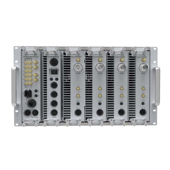
Power Supply Unit (PSU) High Power Remote Module (HPR) Optical Remote Unit (ORU) Power Supply Unit (PSU) High Power Remote Module (HPR) Optical Remote Unit (ORU) Ground Terminal Figure 1-2 ADXV-HPR Quick View (Front and Rear) Advanced RF Technologies, Inc. -
Page 14: Warnings And Hazards
Opening the ADXV-HPR could result in electric shock and may cause severe injury. WARNING! EXPOSURE TO RF Working with the ADXV-HPR while in operation, may expose the technician to RF electromagnetic fields that exceed FCC rules for human exposure. Visit the FCC website at www.fcc.gov/oet/rfsafety to learn more about the effects of exposure to RF electromagnetic fields. - Page 15 WARRANTY Opening or tampering the ADXV-HPR will void all warranties. Lithium Battery: CAUTION. RISK OF EXPLOSION IF BATTERY IS REPLACED BY INCORRECT TYPE. DISPOSE OF USED BATTERIES ACCORDING TO INSTADXV-HPRCTIONS. Ethernet Instructions: This equipment is for indoor use only. All cabling should be limited to inside the building.
- Page 16 Laser Safety Fiber optic ports of the ADXV-HPR emit invisible laser radiation at the 1310, 1550nm wavelength window. To avoid eye injury never look directly into the optical ports, patch cords or optical cables. Do not stare into beam or view directly with optical instruments. Always assume optical output is on.
- Page 17 CAUTION Double Pole/Neutral Fusing. Permanent earthing for PERMANENTLY CONNECTED EQUIPMENT, a readily accessible disconnect device shall be incorporated external to the equipment; WARNING: This is NOT a CONSUMER device. It is designed for installation by an installer approved by an ISED licensee. You MUST have an ISED LICENCE or the express consent of an ISED licensee to operate this device.
- Page 18 RF Radiation Exposure This equipment complies with RF radiation exposure limits set forth for an uncontrolled environment. This equipment should be installed and operated with a minimum distance of 600 cm between the radiator and your body. This transmitter must not be co-located or operating in conjunction with any other antenna or transmitter.
-
Page 19: Block Diagram
2. BLOCK DIAGRAM 2.1 ADXV Block Diagram Common DL IN V/UHF(136~512) DL IN (698~2690) ODU#1 UL OUT V/UHF(136~512) Common UL OUT (698~2690) Common 700L Common 700U Common Duplexer Duplexer Duplexer Duplexer Figure 2-1 ADXV Block Diagram Advanced RF Technologies, Inc. -
Page 20: Adxv Scalability
No limitation in 12 slots except NMS No limitation in 12 slots except NMS No limitation in 12 slots except NMS Optic Unit In case of Aux, No limit in 8 Aux ports ADXV-HPR Adaptor type 1 per Remote Module(RM) ADXV-HPR 19” rack mount... -
Page 21: Adxv Overview
3. ADXV OVERVIEW 3.1 Head End The head end unit must always be connected to the Base Station using a direct cabled connection. This system has not been approved for use with a wireless connection via server antenna to the base station. •... -
Page 22: Leds
3.1.1.1 LEDs NMS has LEDs on the front panel as shown in Figure 3-3. POWER LINK Figure 3-3 NMS LED Table 3-1 NMS LED Specifications ADXV-HPR-NMS Specifications POWER Solid Green NMS power is ON NMS power is OFF LINK Solid Red... -
Page 23: Ethernet Port
Alarm Low Impedance (Short) 3.1.1.3 Ethernet Port The Ethernet port can be used to communicate directly with the ADXV-HPR using a RJ-45 crossover cable or can also be used to connect the ADXV-HPR to an external modem box. LAN0 LAN1... -
Page 24: Power Connection (For Dc -48V)
LAN0 HOST REMOTE Figure 3-6 Host/Remote Switch Host IP: 192.168.63.1 (Fixed IP, unable to modify this IP address) • • Remote IP: 192.168.63.5 (Default IP, but can be modified in Host mode) 3.1.1.5 Power Connection (for DC -48V) NMS has terminal block for DC power connection on the front panel. You should verify power polarity of each power line and should turn on the power after power connection necessarily. -
Page 25: Poi (Adxv-H-Poi-X)
3.1.2 POI (ADXV-H-POI-x) ADXV-H-POI-X DL/UL Figure 3-7 POI front View • Functions and features Provide RF interface with BTS Each POI has independent gain control and filtering Modular type and hot swappable Supports duplex port and simplex RX port Easily support additional frequency bands by adding a single POI Reduces complexity and overall equipment size Specifications •... -
Page 26: Rf Ports
Combines DL signals received from each POI and feeds the combined signals to the ADXV-H-ODU Combines UL signals received from each ADXV-HPR and feeds the combined signal to the ADXV-H- No limit of installation number and location to install POI, ODU, CHC card in 12 slots except NMS card •... -
Page 27: Rf Ports
3.1.3.1 RF ports 3.1.3.1.1 RF ports at the front panel (DL 1 to DL 8, UL 1 to UL 8) DL 1(to DL 8) & UL 1(to UL 8) RF ports are connected to DL OUT/UL IN Ports at the front panel of POI. Receive the downlink signal from each POI •... -
Page 28: Rf Ports
LINK 1 Figure 3-13 ODU Optic Ports The ADXV-H-ODU4 has (4) optic ports and can support up to (4) Main ADXV-HPR’s. Likewise, the ADXV-H-ODU1 has (1) optic ports and can support up to (1) Main ADXV-HPR. Advanced RF Technologies, Inc. -
Page 29: Remote Unit (Adxv-Hpr)
3.2 ADXV-HPR A remote unit (single ADXV-HPR chassis base) is composed of an ADXV-HPR-ORU (Optical Remote Unit), a PSU (Power Supply Unit) and plural band’s RM (Remote Module). Specifications • Size: 19.0 x 14.96 x 7 inches (482 x 380 x 178 mm) Weight: 62.17lbs (28.2 Kg)@4 HPR(437F/43S8C/46P/46A), ADXV-HPR-ORU and PSU... -
Page 30: Remote Module (Adxv-Hpr-4Xx)
Weight: 13.22lbs for 437F, 43S8C, 46P, 46A, 45W, 46BT 3.2.1.1 HPR ID numbering and RF line connection scheme HPR ID right next to ADXV-HPR-ORU is HPR #1, HPR second next is HPR #2, the rest of HPR s’ ID numbering is in the same order. -
Page 31: Rf Port
Figure 3-16 ADXV-HPR ID numbering and RF connection between ADXV-HPR-ORU and ADXV-HPR 3.2.1.2 RF port DL IN/UL OUT connect to ADXV-HPR-ORU’s DL port and UL port, it is necessary to connect UL’s port number equal to DL’s because of serial communication with ADXV-HPR-ORU. -
Page 32: Front Port
Weight: 11.02lbs 3.2.2.1 Front port DL1-DL6: DL port connect to ‘DL IN’ of ADXV-HPR (Remote Module) (see 3.2.1.1) UL1-UL6: UL port connect to ‘UL OUT’ of ADXV-HPR (Remote Module)(see 3.2.1.1) E-DL/E-UL ports connect to external splitter for extension of band RM... -
Page 33: Psu (Adxv-Hpr-Psu)
Weight: 11.02lbs for AC/DC PSU 3.2.3.1 Port ADXV-HPR1-ADXV-HPR4 ports connect respectively to ADXV-HPR’s front port. ADXV-HPR-ORU port connects to ADXV-HPR. ALARM port connects to ‘PSU ALARM’ port of ADXV-HPR-ORU ALARM port AC IN 110V port connects to AC 110V Advanced RF Technologies, Inc. -
Page 34: Led
(WARNING: The AC switch must be set to OFF before cable connection to avoid equipment damage and personal injury.) (WARNING: To avoid damage, be sure 110V AC for operation of ADXV-HPR.) (CAUTION: DOUBLE POLE/NEUTRAL FUSING.) The procedure for connecting ADXV-HPR AC S/W OFF ... -
Page 35: Remote Unit Connection Diagrams
4.2 Remote Unit Connection Diagrams HPR #1 HPR #2 HPR #3 HPR #4 HPR #1 HPR #2 HPR #3 HPR #4 Figure 4-2 ADXV-HPR 4ands connection Advanced RF Technologies, Inc. -
Page 36: Mounting Method
5. MOUNTING METHOD 5.1 Head End 5.1.1 Rack Mount ADXV-H-NMS-DC ADXV-H-POI-X ADXV-H-POI-X ADXV-H-POI-X ADXV-H-POI-X ADXV-H-POI-X ADXV-H-CHC-88-DL ADXV-H-CHC-88-UL ADXV-H-ODU-4 LAN0 HOST REMOTE DL/UL DL/UL LAN0 AUX 1 AUX 1 LAN1 AUX 3 AUX 3 LINK SERVICE AUX 5 AUX 5 P(+) N(-) DL/UL DL/UL... -
Page 37: Adxv-Hpr
Open and check each package against the packing list. If any items are missing, contact ADRF customer service. -
Page 38: Adxv Installation Procedure
Pollution degree (PD) 6.2 ADXV Installation Procedure 6.2.1 HE Installation Procedure CAUTION: ADXV- HE should be installed inside building only. 6.2.1.1 Installing a ADXV- HE in a rack The ADXV HE chassis mounts in a standard 19” (483mm) equipment rack. Allow clearance of 3” (76mm) at the front and rear, and 2”... -
Page 39: Figure 6-1 He Installation Procedure
Figure 6-1 HE Installation Procedure Advanced RF Technologies, Inc. -
Page 40: Adxv-Hpr Installation Procedure
2” (51mm) on both sides for air circulation. No top or bottom clearance is required. Consideration: • Eight mounting holes (two holes at each corner of ADXV-HPR rack) are to attach it to the 19” rack. The ADXV-HPR must be securely attached to a rack that can support the weight of the ADXV. •... -
Page 41: Figure 6-2 Adxv-Hpr Installation Procedure
Figure 6-2 ADXV-HPR Installation Procedure Advanced RF Technologies, Inc. -
Page 42: Rf Coaxial Cable And Antenna Connection
6.2.3 RF coaxial cable and antenna connection > The coaxial cables which are connected to antenna port of ADXV-HPR. Before connection, check the VSWR value of coaxial cable whether it is within specification using Site master. > At this time, check if the Return loss have above 15dB or VSWR have below 1.5 >... -
Page 43: Optic Port Cleaning
6.4 Optic Port Cleaning • We recommend cleaning optic connector using a dry optical cleaning swab or tissue in a dry environment as needed. We recommend cleaning the optic connectors only if the expected optic loss is higher than the loss reported in the Web-GUI by 1.5dBo. -
Page 44: Web-Gui
Table 7-1 Account Information for Login Account type Show items Control Items Default ID Default Password Administrator all Items all items admin admin User restricted items restricted items adrf adrf Guest restricted items read-only guest guest Advanced RF Technologies, Inc. -
Page 45: Administrator/User Mode
7.2 Administrator/User Mode 7.2.1 Common 7.2.1.1 Navigation Tree The navigation tree located on the left hand side of the Web-GUI allows the user to switch between the various modules that are connected to the system. Table 7-2 Navigation tree Parameters Description Expands the entire navigation tree Collapses the entire navigation tree... -
Page 46: Figure 7-2 Adxv-Hpr General Information
Install tab. It is recommended to use the location of the module as the description. This description information can be seen when hovering over the device tree in order to easily identify each component. Technical Support: Displays ADRF’s Technical Support contact information. •... -
Page 47: Status Tab
The NMS Status page provides an overall view of how the system is performing. From the NMS Status page, the user can see what modules are connected to ADXV-HPR. In addition, the user can see if any alarms are present in the system and also the commissioning status of each module. -
Page 48: Figure 7-4 Location Setting (Install - Nms)
This section allows the user to input the latitude and the longitude of the repeater. Figure 7-4 Location Setting (Install – NMS) Select N or S from the dropdown menu for Latitude • • Select E or W from the dropdown menu for Longitude •... -
Page 49: Figure 7-7 Snmp Agent False Alarm Test (Install - Nms)
Figure 7-7 SNMP Agent False Alarm Test (Install – NMS) 7.2.2.1.10 Location Info / Installer Info This section allows the user to specify the address of the repeater and also the information of the installer. Figure 7-8 Location Info / Installer Info (Install – NMS) Advanced RF Technologies, Inc. -
Page 50: System
7.2.2.1.11 Date & Time This section allows the user to specify the current date and time. Figure 7-9 Date & Time Setting (Install – NMS) 7.2.2.1.12 Description This section allows the user to save the description of remote module. Figure 7-10 Description (Install-Remote Module) 7.2.3 System The System tab allows the user to perform firmware updates, upload closeout packages, view any changes to... -
Page 51: Figure 7-12 New Account
Figure 7-12 New Account Advanced RF Technologies, Inc. -
Page 52: System: Logs
7.2.3.1.3 System: Account - Change Password The Change Password section allows the current user who is logged into the system to change their login credentials. Figure 7-13 Change Password 7.2.3.2 System: Logs 7.2.3.2.1 System: Logs - Event Log This section displays system events that have taken place. The Event Log displays who has made the changes, the time and date of when the event took place, and what changes were made to the system. -
Page 53: System: Update
7.2.3.3 System: Update • To perform a firmware update, click on the System:Update tab and the following screen will show up. Figure 7-15 System update Click on the ‘Browse’ button and locate the firmware file. • • Click on the Update button to perform the firmware update. •... -
Page 54: Logout
Figure 7-17 Help 7.2.5 Logout Clicking the Logout button will log the current user off the system. 7.3 Guest Mode When logging into the system as a guest, the guest will only have read-only privileges and will not be able to make any changes to the system. - Page 55 Meet FCC, 3GPP TS 36.104, 3GPP2 C.S0010-C Head End 19in x 19.7 in x 7.0 inches Chassis POI/POIL 1.3in x 17.0 in x 6.85 inches Dimension ADXV-HPR 19in x 15.0 in x 10.5 inches (WXDXH) Chassis ADXV- HPR(Remote 2.75in x 17.8 in x 10.3 inches...
- Page 56 Unit) Operating Temperature -22 - 140 F(-30~60°C) Operating Humidity 5~90%RH -48V DC Head-End Power 110/220V, 50-60Hz(optional) with battery backup function Supply 110/220V, 50-60Hz ADXV-HPR -48V DC(optional) ADXV-H-NMS- 8.85 Watt ADXV-H-ODU- 7.47 Watt ADXV-H-POI 7.20 Watt ADXV-H-POIL 6.45 Watt ADXV-HPR- Power PSU-AC 5.4 Watt...
- Page 57 Meet FCC, 3GPP TS 36.104, 3GPP2 C.S0010-C Head End 19in x 19.7 in x 7.0 inches Chassis POI/POIL 1.3in x 17.0 in x 6.85 inches Dimension ADXV-HPR 19in x 15.0 in x 10.5 inches (WXDXH) Chassis ADXV- HPR(Remote 2.75in x 17.8 in x 10.3 inches...
- Page 58 ADXV-HPR- 264 Watt 46BT Network Management Ethernet(RJ45) System DIN(Female) POIL 4.3-10(Female) ADXV- connector HPR(Remote 4.3-10(Female) Unit) "The Manufacturer's rated output power of this equipment is for single carrier operation. For situations when multiple carrier signals are present, the rating would have to be reduced by 3.5 dB, especially where the output signal is re-radiated and can cause interference to adjacent band users.
-
Page 59: Figure 9-1 He Drawing
9. MECHANICAL DRAWING 9.1 HE Figure 9-1 HE Drawing Advanced RF Technologies, Inc. - Page 60 9.2 ADXV-HPR Figure 9-2 ADXV-HPR Drawing Advanced RF Technologies, Inc.
Need help?
Do you have a question about the ADXV-HPR and is the answer not in the manual?
Questions and answers