Table of Contents
Advertisement
Quick Links
PRO-360 Series Controllers
Section
1.
Introduction ................................. 2
Do's and Don'ts .......................... 2
2.
3.
Getting Started ............................ 3
4.
Control Connections .................. 4
5.
Simple wiring diagram ............... 5
6.
Auxiliary Input 1 .......................... 6
7.
Auxiliary Input 2 .......................... 6
8.
Thermistor input ......................... 7
9.
Radio Control Input and BEC .... 7
10. Power Connections .................... 8
11. Display ......................................... 9
12. Programming .............................. 9
13. Forward / Reverse Settings ..... 11
PRO-360 V2.3/4 10/20
Instruction Manual
PRO-360-S/HV
Firmware Version 2.3
Contents
Page Section
Page 1
14. General Settings ....................... 11
15. Throttle settings ....................... 12
16. Advanced settings .................... 12
17. Using the "learn" function ....... 13
18. Power-up options ..................... 14
19. System settings [inc reset] ...... 14
20. Mounting ................................... 15
21. Display mounting...................... 15
22. Fault finding .............................. 16
23. Service ....................................... 16
24. Default profile settings ............. 17
25. Specifications ........................... 19
Page
www.4qd.co.uk
Advertisement
Table of Contents

Related Manuals for 4qd PRO-360 Series

Summary of Contents for 4qd PRO-360 Series
-
Page 1: Table Of Contents
Instruction Manual PRO-360 Series Controllers PRO-360-S/HV Firmware Version 2.3 Contents Section Page Section Page Introduction ......... 2 14. General Settings ....... 11 Do's and Don’ts ......2 15. Throttle settings ....... 12 Getting Started ......3 16. Advanced settings ....12 17. -
Page 2: Introduction
• Do fit a motor suppression capacitor, and ferrite rings. • Do twist the motor wires together if possible. • Do call 4QD if you are uncertain about something. PRO-360 V2.3/4 10/20 Page 2 www.4qd.co.uk... -
Page 3: Getting Started
The Pro-360 is supplied with the keypad and / or display cables not connected to their sockets. These should be plugged in once the Pro-360 has been fixed in position, the control and power connections made, and you are ready to start operation. PRO-360 V2.3/4 10/20 Page 3 www.4qd.co.uk... -
Page 4: Control Connections
Control Connections The control input sockets are shown below. The main control input and brake should be wired as shown below [they are compatible with Pro-120/150 and DNO/VTX installations]. PRO-360 V2.3/4 10/20 Page 4 www.4qd.co.uk... -
Page 5: Simple Wiring Diagram
Simple wiring diagram This diagram shows the basic connections needed to get the Pro-360 running. PRO-360 V2.3/4 10/20 Page 5 www.4qd.co.uk... -
Page 6: Auxiliary Input 1
C - Speed. This pin can be used with our speed sensor kit [part number SEN-SPD] for top speed limiting. The sensor is powered by the BEC supply and delivers a 5V pulse proportional to the speed of the shaft that the magnet is attached to. PRO-360 V2.3/4 10/20 Page 6 www.4qd.co.uk... -
Page 7: Thermistor Input
Thermistor input Can be used to connect 1 or 2 sensors to monitor external temperatures. Sensors X and Y should be 4QD part number SEN-TMP. Sensor X is connected to C and D, Sensor Y to A and B. Once the sensors have been installed they must be enabled in the profile menu. -
Page 8: Power Connections
The Pro-360 has provision to drive a failsafe contactor which can provide an emergency disconnection in the event of a controller failure. Details of how to implement this feature are in the knowledgebase on our website. PRO-360 V2.3/4 10/20 Page 8 www.4qd.co.uk... -
Page 9: Display
To edit the settings the SEL button should be held down while turning on the ignition, you can then navigate through the options and settings as shown in the menu structure below. Remember to use the menu option to save changes. PRO-360 V2.3/4 10/20 Page 9 www.4qd.co.uk... - Page 10 PRO-360 V2.3/4 10/20 Page 10 www.4qd.co.uk...
-
Page 11: Forward / Reverse Settings
Note; There is also a “System current limit” which is not user adjustable. If the load tries to exceed this value a message is shown, and the controller will shut down to protect itself. PRO-360 V2.3/4 10/20 Page 11 www.4qd.co.uk... -
Page 12: Throttle Settings
“Contactor”. Changes the controller to contactor mode. See the knowledge base 16.3 on our website for more details. “E-stop ramp” Sets the time taken to slow down to zero when the E-stop input is 16.4 activated. The default time is 0.5S. PRO-360 V2.3/4 10/20 Page 12 www.4qd.co.uk... -
Page 13: Using The "Learn" Function
If you are not using “Joystick” mode, you should set “Learn max reverse” to the same value as “Learn max forward”. Reverse is then selected by the reverse switch. • Volt mode uses the “Pot learn” function for learning. PRO-360 V2.3/4 10/20 Page 13 www.4qd.co.uk... -
Page 14: Power-Up Options
Switch off the Pro-360, insert the uSD card containing the new software into the card holder, and switch on again with SEL pressed. Navigate through the system settings menu to “Firmware” and then follow instructions. Remove the uSD card when finished. PRO-360 V2.3/4 10/20 Page 14 www.4qd.co.uk... -
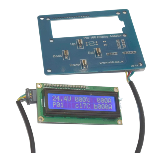
Page 15: Mounting
There is an optional display / adaptor board which combines a display mounting place with an alternative keypad. The display adaptor board and cables can be found on our website. PRO-360 V2.3/4 10/20 Page 15 www.4qd.co.uk... -
Page 16: Fault Finding
The Pro-360 has a 12 month warranty. Please see the service section of our website for full details. It is also worth checking the troubleshooting section of our website for advice on how to find common installation problems. PRO-360 V2.3/4 10/20 Page 16 www.4qd.co.uk... -
Page 17: Default Profile Settings
24. Default profile settings PRO-360 V2.3/4 10/20 Page 17 www.4qd.co.uk... - Page 18 PRO-360 V2.3/4 10/20 Page 18 www.4qd.co.uk...
-
Page 19: Specifications
Emergency stop input Other inputs Deadman, alt profile, speed, 2 x thermistor, 2 x limit, 2 x spare Powerdown state Diode bridge across motor Closed loop RPM control Via software update Ignition, electronic Safety contactor circuit PRO-360 V2.3/4 10/20 Page 19 www.4qd.co.uk... - Page 20 Technical Specification Pro-360 360-S 360-HV Heatsink 10mm plate standard. Advanced air cooled and water cooled available as options. Double heading Y [also comms board coming soon] Switching frequency 20 kHz Quadrants PRO-360 V2.3/4 10/20 Page 20 www.4qd.co.uk...