Table of Contents

Related Manuals for Avanzini DRAGO P1 PLUS


Summary of Contents for Avanzini DRAGO P1 PLUS
- Page 1 TRANSLATION OF THE ORIGINAL INSTRUCTIONS Instruction manual, use and maintenance BURNER DRAGO P1 PLUS AVANZINI BRUCIATORI s.r.l. Via G. Battistini, 11 43122 - Parma (PR) - Italy tel. +39 0521 271344 fax +39 0521 775862 info@avanzinibruciatori.it...
- Page 2 In any case, note that the writing company is always available for any clarifications or additional information. INDEX OF THE REVISIONS NOTES AT REV. No. OF LAST PAGE DATE PUBLICATION 08/2019 COPYRIGHT © 2019 AVANZINI BRUCIATORI s.r.l. Page 2 D r a g o P 1 P L U S...
- Page 3 Instructions, use and maintenance manual TABLE OF CONTENTS D r a g o P 1 P L U S Page 3...
-
Page 4: Table Of Contents
Instructions, use and maintenance manual TABLE OF CONTENTS IDENTIFICATION OF THE MACHINE ............9 1.1. MANUFACTURER IDENTIFICATION .................. 9 1.2. MODEL IDENTIFICATION ....................9 1.3. IDENTIFICATION PLATE ....................10 1.4. DECLARATION OF CONFORMITY (COPY) ..............11 1.5. REFERENCE DIRECTIVES ....................12 GENERAL PRELIMINARY INFORMATION ..........13 2.1. - Page 5 Instructions, use and maintenance manual DESCRIPTION OF THE MACHINE ............27 4.1. INTENDED USE (CORRECT) .................... 28 4.1.1. REASONABLY FORESEEABLE IMPROPER USE ..................28 4.2. OBLIGATIONS AND PROHIBITIONS ................29 4.2.1. USER OBLIGATIONS .............................29 4.2.2. OPERATOR OBLIGATIONS ...........................29 4.2.3. PROHIBITIONS FOR THE OPERATORS ......................30 4.3.
- Page 6 5.9.1. GAS PIPE CONNECTION FROM THE CONTROL PANEL TO THE DISTRIBUTION SYSTEM ....65 5.10. DISMANTLING AND WASTE DISPOSAL ................67 HOW TO USE ..................69 6.1. CONTROL PANEL WITH KNOB DRAGO P1 PLUS ............70 6.2. FIRST IGNITION AND ADJUSTMENT ................71 6.2.1. FIRST IGNITION WITH THE CONTROLS OF THE CONTROL PANEL ............72 6.2.2.
- Page 7 Instructions, use and maintenance manual 7.5.3. FLAME ARRESTOR REPLACEMENT ......................87 7.5.4. FLAME ARRESTORS .............................88 7.5.5. PILOT FLAME AIR ADJUSTMENT .........................89 7.5.6. REPLACEMENT SWITCH-ON BATTERY ......................90 TROUBLESHOOTING ................91 8.1. INTRODUCTION ........................ 91 8.2. MANUFACTURER’S ADVICE .................... 94 ATTACHMENTS ..................95 9.1. TECHNICAL DATA SHEET ....................95 D r a g o P 1 P L U S Page 7...
- Page 8 Instructions, use and maintenance manual PAGE INTENTIONALLY LEFT BLANK Page 8 D r a g o P 1 P L U S...
-
Page 9: Identification Of The Machine
This manual contains confidential information and drawings, property of AVANZINI BRUCIATORI s.r.l. It is forbidden to even partially reproduce the manual without the written authorisation of AVANZINI BRUCIATORI s.r.l. D r a g o P 1 P L U S... -
Page 10: Identification Plate
1.3. IDENTIFICATION PLATE For machine identification purposes, a special identification plate was affixed to the machine; the identification data indicated on this plate must be reported to AVANZINI BRUCIATORI s.r.l. every time a service call is requested or when ordering spare parts: POS. -
Page 11: Declaration Of Conformity (Copy)
DRAGO / P1 Plus – NATURAL REGISTRATION NUMBER P1 Plus/**** The undersigned Andrea Avanzini in quality of Legal Representative of the company Avanzini Bruciatori S.r.l. DECLARES under his own responsibility that the equipment concerned conforms to directives : Directive 2014/30/EU regarding electromagnetic compatibility. -
Page 12: Reference Directives
Instructions, use and maintenance manual 1.5. REFERENCE DIRECTIVES The equipment supplied by AVANZINI BRUCIATORI s.r.l. complies with the directives: • Directive 2014/35/EU on low voltage, relative to safety guarantees that electrical material must possess when intended for use within certain voltage limits. -
Page 13: General Preliminary Information
Instructions, use and maintenance manual 2. GENERAL PRELIMINARY INFORMATION 2.1. MANUFACTURER IDENTIFICATION The manual is intended for operators in charge of using and managing the plant in all the technical phases of its service life. It also contains the subjects regarding the proper use of the machine, in order to maintain the functional and qualitative features of the machine unaltered over time. -
Page 14: Language
Instructions, use and maintenance manual 2.4. LANGUAGE The original manual was edited in Italian. Any translations into other languages must be done from the original instructions. The Manufacturer considers itself responsible for the information in the original instructions. Translations in other languages cannot be fully verified, therefore, in case of a detected inconsistency, respect the text in the original language or contact our Technical Documentation Department. -
Page 15: Manual
Instructions, use and maintenance manual 2.5. MANUAL PAGE STRUCTURE The master pages of this manual are structured so as to provide the user with important information on whatever page he/she is on: LEFT PAGE RIGHT PAGE POS. ELEMENT DOCUMENT TITLE CHAPTER NUMBER PAGE NUMBER COMPANY LOGO... -
Page 16: Operator Qualifications
Instructions, use and maintenance manual 2.6. OPERATOR QUALIFICATIONS Refer to the following table to establish with certainty what skills and qualifications are required of the operators in charge of the various duties (starting up, cleaning, routine maintenance): QUALIFICATION DEFINITION This is the user's trained staff authorised to use and run the machine for production purposes, for the activities it was built and supplied for. - Page 17 EQUIPMENT Personnel in charge of using the material ad machine lifting and handling means (scrupulously following the instructions of AVANZINI BRUCIATORI s.r.l., in compliance with the laws in force in the country of the machine user. Qualified engineer able to: •...
-
Page 18: Symbols Used In The Manual
Instructions, use and maintenance manual 2.7. SYMBOLS USED IN THE MANUAL SYMBOL DESCRIPTION Symbol used to identify particularly important information in the manual. The information also regards the safety of personnel involved in use of the machine. Symbol used to indicate warnings or procedures related to operator safety. Symbol used to indicate warnings or procedures related to electrical power. -
Page 19: Terminology Used
Instructions, use and maintenance manual 2.8. TERMINOLOGY USED Technical terminology or different meaning from the ordinary used in the manuals. Below is an explanation of the terms and abbreviations used: TERM DESCRIPTION Device that, after machine commissioning, is assembled to the machine by the same EQUIPMENT operator in order to modify its function or attribute a new function, in so far as such INTERCHANGEABLE... -
Page 20: Safety Pictograms
CAUTION! IT IS STRICTLY FORBIDDEN TO REMOVE THE WARNING PLATES ON THE MACHINE. AVANZINI BRUCIATORI s.r.l. will not be held liable for the safety of the machine should this prohibition be disregarded. CAUTION! The user must replace warning signs which have become illegible due to wear. -
Page 21: Personal Protective Equipment
Instructions, use and maintenance manual 2.10. PERSONAL PROTECTIVE EQUIPMENT When operating near the machine for assembly and maintenance and/or adjustment operations strictly respect the main accident-prevention rules. For this purpose it will be important to use the personal protective equipment (P.P.E.) required for each individual operation. -
Page 22: Warranty
• The right to services under warranty is only acknowledged if it is reported to AVANZINI BRUCIATORI s.r.l. as soon as the defect is noted and simultaneously submitting the relevant repair order. -
Page 23: Safeties
Removing or tampering with the safety devices implies a dangerous situation for the operator, which could result in a serious accident that could lead to serious physical harm. Removing or tampering with safety devices relieves AVANZINI BRUCIATORI s.r.l. from any kind of civil or criminal liability and/or any compensation towards the injured party. -
Page 24: Noise
Instructions, use and maintenance manual 3.2. NOISE The noise levels have been measured in accordance with the requirements of UNI EN 11200 and UNI EN ISO 3746. During the operating cycles, the levels of exposure to noise for appointed personnel do not exceed 76 dB. The actual noise levels of the installed machine during operation on site in a manufacturing process differ from those detected, as the noise is influenced by factors such as: •... - Page 25 Instructions, use and maintenance manual RISK DESCRIPTION AND PROCEDURAL INFORMATION Handling procedures are described in this instructions manual in the “Transport, handling and installation” chapter. RISKS DUE TO HANDLING The following operations: Necessary PPE • unloading the packages; • opening the packages; •...
- Page 26 Instructions, use and maintenance manual RISK DESCRIPTION AND PROCEDURAL INFORMATION The machine is not suitable to operate in explosive or classified environments. RISK OF EXPLOSIVE ATMOSPHERE Using it in explosive or partially explosive atmospheres is strictly prohibited. Necessary PPE The machine is therefore not suitable to work in the following environments: •...
-
Page 27: Description Of The Machine
Instructions, use and maintenance manual 4. DESCRIPTION OF THE MACHINE In order to assure the maximum operating reliability, AVANZINI BRUCIATORI s.r.l. has carefully chosen the materials and components used in constructing the machinery, having it undergo a regular test inspection before delivery. -
Page 28: Intended Use (Correct)
Instructions, use and maintenance manual 4.1. INTENDED USE (CORRECT) The machine described in this manual called “BurnerDrago P1 PLUS” was designed and built to heat up ovens for the purpose of baking bread and pizza. The machine is intended for: INTENDED USE UNINTENDED WORK ENVIRONMENT... -
Page 29: Obligations And Prohibitions
Instructions, use and maintenance manual 4.2. OBLIGATIONS AND PROHIBITIONS 4.2.1. USER OBLIGATIONS The user (entrepreneur or employer) must: • consider the abilities and conditions of the operators in relation to their health and safety; • provide personal protective equipment appropriate to the individual procedures; •... -
Page 30: Prohibitions For The Operators
(consult chap. 5). CAUTION! The company AVANZINI BRUCIATORI s.r.l. is not liable for damages to property or people if it has been ascertained that the machine has been used in one of the above environments. -
Page 31: Technical Data
Instructions, use and maintenance manual 4.3. TECHNICAL DATA BURNER LENGTH 200 mm BURNER WIDTH 200 mm BURNER HEIGHT 200 - 400 mm CONTROL UNIT DEPTH 200 mm CONTROL UNIT WIDTH 200 mm CONTROL UNIT HEIGHT 200 mm BATTERY AA 1.5 V TOTAL MASS 7 kg CAUTION! -
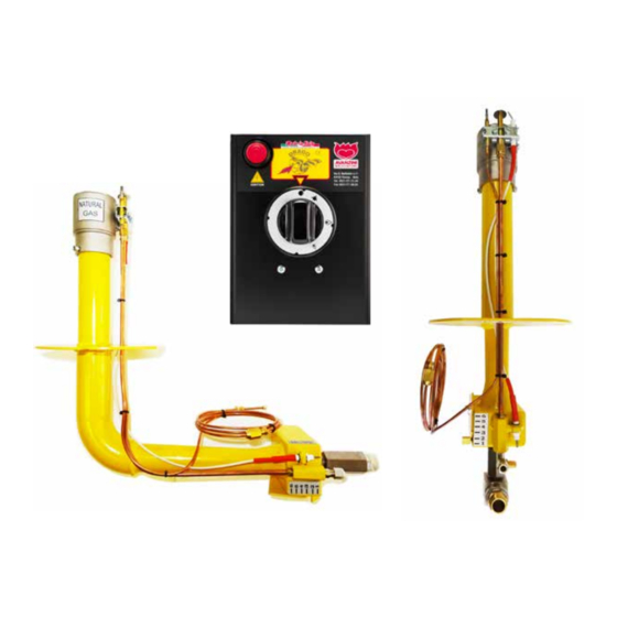
Page 32: Main Components
Instructions, use and maintenance manual 4.4. MAIN COMPONENTS POS. ELEMENT MANUAL CONTROL PANEL WITH KNOB IGNITION KNOB AND FLAME ADJUSTMENT PILOT FLAME IGNITION BUTTON OR ON BUTTON BURNER FIXING FLANGE THERMOCOUPLE TIP GAS CONNECTION FITTING (from the control panel with knob to the burner) ELECTRICAL IGNITION CONNECTION PILOT FLAME GAS PIPE FITTING AIR REGULATOR... - Page 33 Instructions, use and maintenance manual D r a g o P 1 P L U S Page 33...
-
Page 34: Work Cycle
Instructions, use and maintenance manual 4.5. WORK CYCLE The machine is designed to heat a food industry oven for baking bread and/or pizza. The operator turns on the burner pilot flame using the controls on the control panel; using the ignition and flame adjustment knob, the operator can raise or lower the intensity of the flame and consequently, the internal temperature of the oven. -
Page 35: Transport And Installation
To handle the machine, respect the indications and pictograms shown, using suitable tools and equipment. During installation, the AVANZINI BRUCIATORI s.r.l. technicians must be assisted by operators who are assigned for future maintenance and operation of the machine. The machine was designed in such a way as to not require the use of equipment such as cranes, gantries or forklift trucks during the packaging, transport and assembly phases. -
Page 36: Packaging
CAUTION! Before opening the packaging, its integrity must be checked and any anomalies must be communicated to AVANZINI BRUCIATORI s.r.l. Upon receipt of the machine, the customer must verify that there are no damages caused by the method of transport or by the personnel in charge of the specific operations. -
Page 37: Transport And Handling
Instructions, use and maintenance manual 5.3. TRANSPORT AND HANDLING AVANZINI BRUCIATORI s.r.l., uses the most appropriate packing and fastening materials based on machine type and mode of transportation to ensure the machine is not damaged during shipping. The handling procedures described in this paragraph shall be carried out by staff trained for such operations;... -
Page 38: Table Of Units And Of Weights
The above data is described in the relative paragraphs. CAUTION! All external power supply connections to the machine must be made during installation by AVANZINI BRUCIATORI s.r.l. personnel. 5.5. INSTALLATION ENVIRONMENT The installation environment is crucial for proper burner operation, since it has to guarantee proper air contribution to the burner. -
Page 39: Oven Installed Indoors
Instructions, use and maintenance manual IMPORTANT! The installation environment must be free of draughts that may cause malfunctions, such as irregular flames or burner shut-downs. If the characteristics of the installation environment make it impossible to eliminate any existing draughts, (e.g., oven installed in an room with 2 windows opposite each other), the base of the oven must be closed on the sides and in the rear (leaving only the front side open) so as to protect the burner from draughts without however isolating it from the environment, and air intake is still possible. -
Page 40: Oven Installed Outdoors, With Oven Loading Door In Aseparate Room (Indoors)
Instructions, use and maintenance manual 5.5.3. OVEN INSTALLED OUTDOORS, WITH OVEN LOADING DOOR IN A SEPARATE ROOM (INDOORS) In this case, the oven in which the burner is installed is outdoors, while the oven loading door is positioned indoors. However, for proper operation, the burner and the oven loading door have to take in air from the same environment in order to avoid pressure differences that may result in malfunctions. -
Page 41: Oven Installed Outdoors
Instructions, use and maintenance manual 5.5.4. OVEN INSTALLED OUTDOORS To install the oven outdoors, follow the same instructions provided in item 5.5.3. Close the oven base on the 2 sides and in the rear, leaving the front part under the oven loading door open. This configuration will prevent any draughts that would interfere with proper burner operation. -
Page 42: Operations On Oven Installations
5.6.1. HOLE IN THE COOKING TOP The Drago P1 PLUS burner is installed in the surface of the oven; the extensions of the torches have to pass through the oven base, until they reach the level of the cooking surface. -
Page 43: Position For Temperature Measurement
Instructions, use and maintenance manual 5.6.2. POSITION FOR TEMPERATURE MEASUREMENT The ideal position for measuring the temperature is on the side opposite the burner. IMPORTANT! THE PROBE MUST ALWAYS BE POSITIONED ON THE SIDE OPPOSITE THE BURNER (Ex. if the burner is on the right, the probe must be positioned on the left). BURNER o 110 mm HOLE... -
Page 44: Hole For The Temperature Probe
Good burner operation depends on the proper positioning of the temperature probe. Make sure you position the temperature probe in compliance with the specifications recommended by AVANZINI BRUCIATORI s.r.l. CAUTION! If the oven does not have a temperature signalling probe, it is possible to request one as an option from AVANZINI BRUCIATORI s.r.l. -
Page 45: Flue
In case the flue need to run horizontally in some sections, increase its length by 2 vertical metres for each horizontal metre. For better burner operation AVANZINI BRUCIATORI s.r.l. recommends the installation of a draught regulator, in order to regulate the amount of heat to vent from the oven through the negative pressure of the chimney. -
Page 46: Installing The Burner
Instructions, use and maintenance manual 5.7. INSTALLING THE BURNER Once the hole has been created in the cooking base, you can proceed to install the burner in the oven; please refer to the procedure described below for burner installation. 5.7.1. FIXING THE FLANGE WITH SLEEVE Each flange with sleeve is customised to fit the Customer’s oven, on the basis of the indications provided at the time of the order. -
Page 47: Verify Positioning Of The Ignition Electrode
Instructions, use and maintenance manual 5.7.2. VERIFY POSITIONING OF THE IGNITION ELECTRODE Before inserting the burner in the flange, check that the ignition electrode is positioned correctly. The spark generated by the ignition electrode must discharge on the edge of the upper plate of the pilot flame. CAUTION! The tip of the electrode must be about 3 millimetres from the pilot plate. -
Page 48: Securing The Burner
Instructions, use and maintenance manual 5.7.3. SECURING THE BURNER Each flange is supplied with coupling points for the burner, made of a spacer, wide-band washer, 8 MA stud and 8 MA nut. STEP ACTION PICTURE Insert the burner into the flange with sleeve, making sure that the three studs of the flange are matched up with the burner eyelets. -
Page 49: Securing The Control Panel With Knob
Instructions, use and maintenance manual 5.7.4. SECURING THE CONTROL PANEL WITH KNOB STEP ACTION Identify the best position where to install the control panel (one ideal position is at the side of the oven loading door, since it can be easily accessed by the operator yet it is protected against potential collisions). -
Page 50: Positioning The Temperature Probe - Optional
Instructions, use and maintenance manual 5.7.5. POSITIONING THE TEMPERATURE PROBE - OPTIONAL Proceed as follows to position the temperature probe: STEP ACTION PICTURE Insert the temperature probe in the previously made hole: • 30-40 mm above the cooking surface (Fig. “A”); Insert the probe so that the bulb fully enters the cooking chamber and place it parallel to the cupola, without it touching the side or... - Page 51 Instructions, use and maintenance manual PAGE INTENTIONALLY LEFT BLANK D r a g o P 1 P L U S Page 51...
-
Page 52: Connections
Instructions, use and maintenance manual 5.8. CONNECTIONS To start the Drago P1 PLUS, secure the necessary connections: TYPE 1/2” GAS PIPE connection (supplied) from the control panel to the burner. TYPE THERMOCOUPLE connection from the burner to the control panel. - Page 53 Instructions, use and maintenance manual TYPE Pilot flame COPPER PIPE d.6 connection (supplied) from the burner to the control panel. TYPE IGNITION ELECTRODE connection from the control panel to the burner. D r a g o P 1 P L U S Page 53...
-
Page 54: Gas Pipe Connection From The Burner To The Control Panel
Instructions, use and maintenance manual 5.8.1. GAS PIPE CONNECTION FROM THE BURNER TO THE CONTROL PANEL WITH A KNOB Page 54 D r a g o P 1 P L U S... - Page 55 Instructions, use and maintenance manual Make the connection by following the steps below: STEP ACTION PICTURE Take the end of the connection pipe “A” (supplied) and wrap the connection thread “B” with Teflon. Tighten the connection pipe “A” to the connection of the control panel “C”...
-
Page 56: Thermocouple Connection From The Burner To The Control Panel
Instructions, use and maintenance manual 5.8.2. THERMOCOUPLE CONNECTION FROM THE BURNER TO THE CON- TROL PANEL WITH A KNOB Page 56 D r a g o P 1 P L U S... - Page 57 Instructions, use and maintenance manual Make the connection by following the steps below: STEP ACTION PICTURE Unroll the thermocouple “E” leaving the burner. CAUTION! careful shape thermocouple with wide curves so as not to damage it. Insert the screw-on end of the thermocouple “E”...
-
Page 58: Copper Pipe (Pilot Flame) Connection From The Burner To The Control Panel
Instructions, use and maintenance manual 5.8.3. COPPER PIPE (PILOT FLAME) CONNECTION FROM THE BURNER TO THE CONTROL PANEL WITH A KNOB Page 58 D r a g o P 1 P L U S... - Page 59 Instructions, use and maintenance manual Make the connection by following the steps below: STEP ACTION PICTURE Unroll the copper pipe “G” (supplied) and insert the end into the grip point “H” of the burner. CAUTION! careful shape copper pipe with wide curves so as not to damage it.
-
Page 60: Ignition Electrode Connection From The Control Panel To The Burner
Instructions, use and maintenance manual 5.8.4. IGNITION ELECTRODE CONNECTION FROM THE CONTROL PANEL WITH A KNOB TO THE BURNER Page 60 D r a g o P 1 P L U S... - Page 61 Instructions, use and maintenance manual Make the connection by following the steps below: STEP ACTION PICTURE Cut the plastic clamp that holds the cable. Completely unroll the white cable “M” leaving the control panel. Insert the end of the white cable “M” into the connection point “N”...
-
Page 62: Connections
Do not use the burner with gases other than the ones indicated on the CE plate. AVANZINI BRUCIATORI s.r.l. declines any and all responsibility with regards to faults resulting from the use of gases other than the ones indicated on the CE plate of the burner. - Page 63 Instructions, use and maintenance manual 5.9.4.1. NATURAL GAS CONNECTION Follow the procedure below to connect to the natural gas network: STEP ACTION PICTURE Connect the gas supply to the 1/2” male fitting “A” on the burner with a flexible hose (not supplied). Make sure the pressure is included between 17 and 23 mbar.
- Page 64 6 kg/h calibrated to 30 mbar (visible from the special pressure gauge) and 1/2” piping. All accessories needed for burner connection (with systems that use cylinders) are sold separately; please contact AVANZINI BRUCIATORI s.r.l. for information on how to purchase these accessories. Gas ramp - LPG ø30 manifold with pressure gauge and safety valve.
-
Page 65: Gas Pipe Connection From The Control Panel To The Distribution System
Instructions, use and maintenance manual 5.9.1. GAS PIPE CONNECTION FROM THE CONTROL PANEL WITH A KNOB TO THE DISTRIBUTION SYSTEM CAUTION! PIPE SUPPLIED, REQUESTED AS AN OPTIONAL ACCESSORY. Make the connection by following the steps below: STEP ACTION PICTURE Take the end of the 1/2” connection pipe “O” (optional - NOT SUPPLIED) and its gasket “P”. - Page 66 Instructions, use and maintenance manual 5.9.1.1. VERIFYING THE SUPPLY PRESSURE Below is the procedure to check the supply pressure to the burner: STEP ACTION PICTURE Identify the connection point of the pressure gauge in the bottom part of the control panel (pressure inlet). Loosen the screw cap “D”...
-
Page 67: Dismantling And Waste Disposal
The following operations as well as indications in the manuals of the equipment, machines, partly-completed machinery and components used, supplied by AVANZINI BRUCIATORI s.r.l. as an integral part of the instruction manual, must be taken into consideration for decommissioning. - Page 68 The following operations as well as indications in the manuals of the equipment, machines, partly-completed machinery and components used, supplied by AVANZINI BRUCIATORI s.r.l. as an integral part of the instruction manual, must be taken into consideration for decommissioning purposes.
-
Page 69: How To Use
Instructions, use and maintenance manual 6. HOW TO USE During machine work phases the operator in charge must run the machine in constant respect of the safety devices foreseen, by checking: • the correct positioning of the safety devices; • the correct operation of the safety devices;... -
Page 70: Control Panel With Knob Drago P1 Plus
Instructions, use and maintenance manual 6.1. CONTROL PANEL WITH KNOB DRAGO P1 PLUS All burner functions can be managed from the Drago P1 PLUS control panel, as can be seen below. POS. ICON/BUTTON DESCRIPTION Flame adjustment selector Pilot flame ignition button... -
Page 71: First Ignition And Adjustment
Instructions, use and maintenance manual 6.2. FIRST IGNITION AND ADJUSTMENT Prior to switching on the burner, make sure the oven loading door is open. CAUTION! Before starting the first ignition, check that the type of gas used matches that indicated on the CE plate of the burner and, if required, proceed with the burner conversion, as described in paragraph 7.5. -
Page 72: First Ignition With The Controls Of The Control Panel
Instructions, use and maintenance manual 6.2.1. FIRST IGNITION WITH THE CONTROLS OF THE CONTROL PANEL IMPORTANT! Open the oven loading door prior to switching on the burner. FIRST IGNITION For the first ignition procedure, follow the operations described below: STEP ACTION PICTURE Rotate the control knob and keep it pressed on the... -
Page 73: High Flame Adjustment
Instructions, use and maintenance manual 6.2.2. HIGH FLAME ADJUSTMENT IMPORTANT! All burners are adjusted by our technicians before being shipped. To change the factory settings, carry out the procedure described below. For the high flame adjustment procedure, carry out the operations described below: STEP ACTION PICTURE... - Page 74 Instructions, use and maintenance manual STEP ACTION PICTURE Check the flame colour in connection with the air flow. See paragraph 6.2.4 Once the flame adjustment procedure is completed, refit the knob “A”. IMPORTANT! The HIGH FLAME is preset – use the knob to vary the heat required according to the product that is to be cooked.
-
Page 75: Low Flame Adjustment
Instructions, use and maintenance manual 6.2.3. LOW FLAME ADJUSTMENT IMPORTANT! All burners are adjusted by our technicians before being shipped. To change the factory settings, carry out the procedure described below. For the low flame adjustment procedure, carry out the operations described below: STEP ACTION PICTURE... - Page 76 Instructions, use and maintenance manual STEP ACTION PICTURE Check the flame colour in connection with the air flow. The flame must be soft, silent and yellow, but it must not colour the cupola of the oven: • Methane: open the damper to position 3.5/4. •...
-
Page 77: Flame Air Adjustment
Instructions, use and maintenance manual 6.2.4. FLAME AIR ADJUSTMENT IMPORTANT! All burners are adjusted by our technicians before being shipped. To change the factory settings, carry out the procedure described here below. For the flame air adjustment, follow the procedure below: STEP ACTION PICTURE... -
Page 78: Switch-Off While Maintaining The Pilot Flame
Instructions, use and maintenance manual 6.2.5. SWITCH-OFF WHILE MAINTAINING THE PILOT FLAME Follow the procedure below to switch off the cooking flame, while keeping the pilot flame on for a subsequent restart: STEP ACTION PICTURE Rotate the control knob to “A”. 6.2.6. -
Page 79: Maintenance
Instructions, use and maintenance manual 7. MAINTENANCE 7.1. INTRODUCTION CAUTION! The maintenance operations must be carried out by qualified and authorised personnel. Burner maintenance includes activities (inspection, check, adjustment and replacement) that become necessary following regular use of the burner. For proper maintenance operations: •... -
Page 80: Safety Warnings
Instructions, use and maintenance manual 7.2. SAFETY WARNINGS CAUTION! For the maintenance activities, close the gas supply system. • Maintenance operators are required to wear all of the personal protective equipment (gloves, goggles) necessary to perform the operation. • During maintenance operations, unauthorised staff must stay out of the relative operating area. •... -
Page 81: Routine Maintenance
Instructions, use and maintenance manual 7.3. ROUTINE MAINTENANCE When the burner is delivered to the user, it is already adjusted for correct operation; nonetheless, to ensure good operation over time, it is necessary to carry out checks as well as periodic and preventive maintenance. Routine maintenance includes inspections, checks and interventions that, in order to prevent faults, monitor: •... -
Page 82: Machine Cleaning
Instructions, use and maintenance manual 7.3.2. MACHINE CLEANING CAUTION! Before starting any cleaning operation on the machine, isolate and padlock all energy sources and safely lock the mobile units composing it. Affix the sign "Machine being serviced - do not power" near the main switch. -
Page 83: Special Maintenance
CAUTION! The spare parts to be replaced are to be ordered from AVANZINI BRUCIATORI s.r.l. Should the customer not use genuine spare parts or parts authorised in writing by the Manufactur- er, the latter shall be relieved of any liability as regards machine operation and operators' safety. -
Page 84: Burner Gas Conversion
7.5. BURNER GAS CONVERSION CAUTION! The conversion operation requires the purchase of the special conversion kit, which contains a nozzle; contact AVANZINI BRUCIATORI s.r.l. to obtain all information on how to purchase the conversion kit; 7.5.1. NOZZLE COMPOSITION Below are the main components of the nozzle: POS. -
Page 85: Nozzle Replacement
Instructions, use and maintenance manual 7.5.2. NOZZLE REPLACEMENT For the gas nozzles replacement procedure, carry out the operations described below: STEP ACTION PICTURE Use a Ø4 mm spanner to loosen and remove screw “D” to fully open the partition. Use a 13 mm spanner to dismantle the stud bolt “B”... - Page 86 Instructions, use and maintenance manual STEP ACTION PICTURE Fasten stud bolt “B” and nozzle “A” to fitting “C”. Tighten screw “D” again to fasten the partition. CHARACTERISTICS OF ALTERNATIVE NOZZLES GAS PRESSURE: NOZZLES FOR METHANE GAS 20 mbar: • with burner on, minimum 13 mbar, maximum 20 mbar; Nozzle diameter 3.75 millimetres •...
-
Page 87: Flame Arrestor Replacement
Instructions, use and maintenance manual 7.5.3. FLAME ARRESTOR REPLACEMENT For the flame arrestors replacement procedure, carry out the operations described below: STEP ACTION PICTURE Loosen screws “A” located on the right side with a cross-head screwdriver. Loosen the Allen screws “B” (ø 4mm), marking down their position for the subsequent fixing of the new flame arrestor. -
Page 88: Flame Arrestors
Instructions, use and maintenance manual 7.5.4. FLAME ARRESTORS Below please find the different types of flame arrestors: TYPE PICTURE METHANE GAS NATURAL GAS A = Ø 60 B = Ø 50 Page 88 D r a g o P 1 P L U S... -
Page 89: Pilot Flame Air Adjustment
Instructions, use and maintenance manual 7.5.5. PILOT FLAME AIR ADJUSTMENT in case of conversion to natural gas or LPG, adjust the pilot flame air as shown below: TYPE PICTURE OPEN LPG SUPPLY 1/2 CLOSED NATURAL GAS SUPPLY D r a g o P 1 P L U S Page 89... -
Page 90: Replacement Switch-On Battery
Instructions, use and maintenance manual 7.5.6. REPLACEMENT SWITCH-ON BATTERY For the ignition battery replacement procedure, carry out the operations described below: STEP ACTION PICTURE Unscrew and remove the power button “A”. Remove the old battery and insert a new battery in the compartment “B”, complying with the polarity. -
Page 91: Troubleshooting
Instructions, use and maintenance manual 8. TROUBLESHOOTING 8.1. INTRODUCTION CAUTION! ALL TROUBLESHOOTING OPERATIONS MUST BE CARRIED OUT WITH THE BURNER SWITCHED OFF. PROBLEM CAUSE SOLUTION THE START BUTTON IS PRESSED ON THE • Replace the batteries (see par. 7.5.3); CONTROL PANEL •... - Page 92 Instructions, use and maintenance manual PROBLEM CAUSE SOLUTION • Purge the copper pipe that brings the gas to the pilot flame. THE PILOT FLAME • Check the integrity of the thermocouple and replace it if DOES NOT REMAIN necessary. • Check that the thermocouple connections are tight enough.
- Page 93 Instructions, use and maintenance manual PROBLEM CAUSE SOLUTION • Burner (air/gas ratio) not properly adjusted (less air). • Unsuitable environment (proper ventilation suction). • Chimney dirty/closed. • Burner under the oven without oxygen. • Cleaning of the flue in case of conversion of wood-burning oven.
-
Page 94: Manufacturer's Advice
Instructions, use and maintenance manual 8.2. MANUFACTURER’S ADVICE COMBINED USE OF WOOD + GAS With this solution the traditional wood-burning aspect is maintained; wood does not change either the taste or the smell of the product • no cap. • partition between wood and burner: brick laid on its side. -
Page 95: Attachments
The enclosed documentation constitutes an integral part of the "INSTRUCTIONS, USE AND MAINTENANCE MANUAL" of the machine supplied by AVANZINI BRUCIATORI s.r.l.. It must be used as a reference for the use, operation and maintenance of the equipment and components. - Page 96 AVANZINI BRUCIATORI s.r.l. Via G. Battistini, 11 43122 - Parma - (Pr) Italy tel. +39 0521 271344 fax +39 0521 775862 info@avanzinibruciatori.it Updated on: 09/2019...
Need help?
Do you have a question about the DRAGO P1 PLUS and is the answer not in the manual?
Questions and answers
My son has a pizza oven purchased and installed in a new house. Can’t seem to get the burner to lite with a drago p1 plus even manually. Does the battery have to be installed for the ignition. Thought battery may also operate an low voltage selinoid valve for safety
The Avanzini DRAGO P1 PLUS burner requires a battery for ignition, as indicated in the troubleshooting section, which mentions replacing flat batteries if the burner does not start. However, there is no explicit mention in the provided context about a battery being required to operate the low voltage solenoid valve.
This answer is automatically generated