Table of Contents
Advertisement
Quick Links
Advertisement
Table of Contents

Related Manuals for Avanzini DRAGO D1/M


Summary of Contents for Avanzini DRAGO D1/M
- Page 1 TRANSLATION OF THE ORIGINAL INSTRUCTIONS Instruction manual, use and maintenance DRAGO D1/M BURNER AVANZINI BRUCIATORI s.r.l. Via G. Battistini, 11 43122 - Parma (PR) - Italy tel. +39 0521 271344 fax +39 0521 775862 REV.01 info@avanzinibruciatori.it...
- Page 2 In any case, note that the writing company is always available for any clarifications or additional information. INDEX OF THE REVISIONS NOTES AT REV. No. OF LAST PAGE DATE PUBLICATION First version 05/2018 Second version 06/2018 COPYRIGHT © 2018 AVANZINI BRUCIATORI s.r.l. Page 2...
- Page 3 Instructions, use and maintenance manual TABLE OF CONTENTS Page 3...
-
Page 4: Table Of Contents
Instructions, use and maintenance manual TABLE OF CONTENTS IDENTIFICATION OF THE MACHINE ............9 1.1. MANUFACTURER IDENTIFICATION .................. 9 1.2. MODEL IDENTIFICATION ....................9 1.3. IDENTIFICATION PLATE ....................10 1.4. DECLARATION OF CONFORMITY (COPY) ..............11 1.5. REFERENCE DIRECTIVES ....................12 GENERAL PRELIMINARY INFORMATION ..........13 2.1. - Page 5 Instructions, use and maintenance manual DESCRIPTION OF THE MACHINE ............29 4.1. INTENDED USE (CORRECT) .................... 29 4.1.1. REASONABLY FORESEEABLE IMPROPER MISUSE .................30 4.2. OBLIGATIONS AND PROHIBITIONS ................31 4.2.1. USER OBLIGATIONS .............................31 4.2.2. OPERATOR OBLIGATIONS ...........................31 4.2.3. PROHIBITIONS FOR THE OPERATORS ......................32 4.3.
- Page 6 Instructions, use and maintenance manual 5.7. INSTALLING THE BURNER ....................48 5.7.1. FIXING THE FLANGE WITH SLEEVE ......................48 5.7.2. VERIFY POSITIONING OF THE ELECTRODE .....................49 5.7.3. SECURING THE BURNER..........................49 5.7.4. DRAGO BABY SIX CONTROL PANEL FASTENING AND CONNECTION ...........50 5.7.5. POSITIONING THE TEMPERATURE PROBE ....................51 5.8.
- Page 7 Instructions, use and maintenance manual MAINTENANCE ..................77 7.1. INTRODUCTION ........................ 77 7.2. SAFETY WARNINGS ......................78 7.3. ROUTINE MAINTENANCE ....................79 7.3.1. ROUTINE MAINTENANCE TABLE ........................79 7.3.2. MACHINE CLEANING ............................80 7.4. SPECIAL MAINTENANCE ....................81 7.5. BURNER GAS CONVERSION ................... 82 7.5.1.
- Page 8 Instructions, use and maintenance manual PAGE INTENTIONALLY LEFT BLANK Page 8...
-
Page 9: Identification Of The Machine
Instructions, use and maintenance manual 1. IDENTIFICATION OF THE MACHINE 1.1. MANUFACTURER IDENTIFICATION Any request for information or assistance must be sent to: AVANZINI BRUCIATORI s.r.l. Via G. Battistini, 11 43122 Parma (PR) - ITALY MANUFACTURER: Tel. (+39) 0521-271344 Fax (+39) 0521-775862 email: info@avanzinibruciatori.it... -
Page 10: Identification Plate
AVANZINI BRUCIATORI s.r.l. every time a service call is ested or when ordering spare parts POS. -
Page 11: Declaration Of Conformity (Copy)
Instructions, use and maintenance manual 1.4. DECLARATION OF CONFORMITY (COPY) Page 11... -
Page 12: Reference Directives
Instructions, use and maintenance manual 1.5. REFERENCE DIRECTIVES he e ipment s pplied by I s.r.l. complies with the directives • irective on low voltage, relative to safety g arantees that electrical material m st possess when intended for use within certain voltage limits. •... -
Page 13: General Preliminary Information
Instructions, use and maintenance manual 2. GENERAL PRELIMINARY INFORMATION 2.1. MANUFACTURER IDENTIFICATION The manual is intended for operators in charge of using and managing the plant in all the technical phases of its service life. It also contains the subjects regarding the proper use of the machine, in order to maintain the functional and qualitative features of the machine unaltered over time. -
Page 14: Language
Instructions, use and maintenance manual 2.4. LANGUAGE The original manual was edited in Italian. Any translations into other languages must be done from the original instructions. an fact rer considers itself responsible for the information in the original instr ctions. ranslations in other lang ages cannot be f lly verified, therefore, in case of a detected inconsistency, respect the te t in the original language or contact our Technical Documentation Department. -
Page 15: Manual
Instructions, use and maintenance manual 2.5. MANUAL PAGE STRUCTURE The master pages of this manual are structured so as to provide the user with important information on whatever page he/she is on: LEFT PAGE RIGHT PAGE POS. Page 15... -
Page 16: Operator Qualifications
Instructions, use and maintenance manual 2.6. OPERATOR QUALIFICATIONS efer to the following table to establish with certainty what s ills and alifications are re ired of the operators in charge of the various duties (starting up, cleaning, routine maintenance). QUALIFICATION DEFINITION This is the user's trained staff authorised to use and run the machine for production purposes, for the activities it was built and supplied for. - Page 17 Instructions, use and maintenance manual QUALIFICATION DEFINITION MANUFACTURER’S MANUFACTURER echnician alified by the man fact rer and or by its distrib tor for comple operations, as he/she is aware of the constructive production cycle of the machine/plant. This person intervenes in agreement with the user requests. The competencies are, as appropriate, of mechanical and/or electrical and/or electronic and/or software type.
-
Page 18: Symbols Used In The Manual
Instructions, use and maintenance manual 2.7. SYMBOLS USED IN THE MANUAL SYMBOL DESCRIPTION Symbol used to identify particularly important information in the manual. The information also regards the safety of personnel involved in use of the machine. Symbol used to indicate warnings or procedures related to operator safety. Symbol used to indicate warnings or procedures related to electrical power. -
Page 19: Terminology Used
Instructions, use and maintenance manual 2.8. TERMINOLOGY USED echnical terminology or different meaning from the ordinary sed in the man als. elow is an e planation of the terms and abbreviations used: TERM DESCRIPTION Device that, after machine commissioning, is assembled to the machine by the same EQUIPMENT operator in order to modify its function or attribute a new function, in so far as such INTERCHANGEABLE... -
Page 20: Safety Pictograms
Instructions, use and maintenance manual 2.9. SAFETY PICTOGRAMS The machine is equipped with a series of pictograms which serve the purpose of warning the operator of the any residual risks. CAUTION! It is strictly forbidden to remove the warning plates on the machine. .r.l. -
Page 21: Personal Protective Equipment
Instructions, use and maintenance manual 2.10. PERSONAL PROTECTIVE EQUIPMENT When operating near the machine for assembly and maintenance and/or adjustment operations strictly respect the main accident-prevention rules. For this purpose it will be important to use the personal protective equipment (P.P.E.) required for each individual operation. -
Page 22: Warranty
The seller guarantees there are no defects for a period of one year from the date of the invoice considering the current technological stage in relation to the type of machine. The right to services under warranty is only acknowledged if it is reported to AVANZINI BRUCIATORI S.r.l. as •... -
Page 23: Safeties
Instructions, use and maintenance manual 3. SAFETIES 3.1. SAFETY DEVICES In order to guarantee full operator safety and prevent access inside the machine while this is moving, the machine has been fitted with a series of safety devices that, in case of activation, ens re its complete stop. CAUTION! Removing or tampering with the safety devices implies a dangerous situation for the operator, which co ld res lt in a serio s accident that co ld lead to serio s physical harm. -
Page 24: Electrical Cut-Out Switch
Instructions, use and maintenance manual 3.1.1. ELECTRICAL CUT-OUT SWITCH PICTURE DESCRIPTION The Customer is responsible for positioning, upstream the insertion point of the power supply line of the machine in the electrical distrib tion system of the installation site. onnection to the power s pply so rce has to ta e place thro gh a dedicated line made available by the Customer;... -
Page 25: Noise Levels
Instructions, use and maintenance manual 3.2. NOISE LEVELS he noise levels have been meas red in accordance with the re irements of ring the operating cycles, the levels of e pos re to noise for appointed personnel do not e ceed The actual noise levels of the installed machine during operation on site in a manufacturing process differ from those detected, as the noise is in enced by factors s ch as... -
Page 26: Residual Risks
Instructions, use and maintenance manual 3.5. RESIDUAL RISKS his machine was designed to g arantee the essential safety re irements for the operator. afety has been incorporated, as m ch as possible, into the design and constr ction of the machine however, there are ris s from which the operators must be protected, especially during: •... - Page 27 Instructions, use and maintenance manual RISK DESCRIPTION AND PROCEDURAL INFORMATION CLEANING AND MAINTENANCE Cleaning and maintenance procedures are described in this instr ctions man al in the hapter. Necessary PPE he operations e pose operators to the ris of contact with hot s rfaces.
- Page 28 Instructions, use and maintenance manual It is the responsibility of the user to: • analyse the ris s that might occ r d ring handling and installation at his her premises the analyses done on the handling of the machine only too into consideration the characteristics of the same •...
-
Page 29: Description Of The Machine
Instructions, use and maintenance manual 4. DESCRIPTION OF THE MACHINE In order to assure the maximum operating reliability, AVANZINI BRUCIATORI s.r.l. has carefully chosen the materials and components used in constructing the machinery, having it undergo a regular test inspection before delivery. -
Page 30: Reasonably Foreseeable Improper Misuse
Instructions, use and maintenance manual 4.1.1. REASONABLY FORESEEABLE IMPROPER MISUSE Reasonably foreseeable misuse is listed below: • installation with modes different from what has been specified in this ser man al • sing the machine so as to achieve greater prod ction val es than the prescribed limits •... -
Page 31: Obligations And Prohibitions
Instructions, use and maintenance manual 4.2. OBLIGATIONS AND PROHIBITIONS 4.2.1. USER OBLIGATIONS The user (entrepreneur or employer) must: • consider the abilities and conditions of the operators in relation to their health and safety • provide personal protective e ipment appropriate to the individ al proced res •... -
Page 32: Prohibitions For The Operators
(consult chap. 5). CAUTION! The company AVANZINI BRUCIATORI s.r.l. is not liable for damages to property or people if it has been ascertained that the machine has been used in one of the above environments. -
Page 33: Technical Data
Instructions, use and maintenance manual 4.3. TECHNICAL DATA BURNER LENGTH 250 mm BURNER WIDTH 250 mm BURNER HEIGHT 800 ÷ 1100 mm CONTROL UNIT DEPTH 100mm CONTROL UNIT WIDTH 160 mm CONTROL UNIT HEIGHT 200 mm VOLTAGE 230 V FREQUENCY 50 Hz ABSORPTION 0.1 kW... -
Page 34: Main Components
Instructions, use and maintenance manual 4.4. MAIN COMPONENTS POS. ELEMENT GAS INLET CONNECTION Ø 1/2“ TO THE BURNER GAS PRESSURE INLET ELECTRICAL WIRING MULTIPLE SOCKETS CONTROL EQUIPMENT GAS SOLENOID VALVE AIR REGULATOR SAFETY THERMOSTAT WITH AUTOMATIC RESET SWITCHING ON AND FLAME DETECTION CABLE BURNER FIXING FLANGE FLAME FUEL HEAD SWITCHING ON AND FLAME DETECTION ELECTRODE... - Page 35 Instructions, use and maintenance manual Page 35...
-
Page 36: Work Cycle
Instructions, use and maintenance manual 4.5. WORK CYCLE The machine is designed to heat a food industry oven for baking bread and/or pizza. The operator turns on the control unit then sets, if necessary, the temperature required inside the oven. he control nit a tomatically t rns on the ame, the ame of the b rner d ring the first phase has the f nction of heating the oven and maintaining its temperature. -
Page 37: Transport And Installation
To handle the machine, respect the indications and pictograms shown, using suitable tools and equipment. During installation, the AVANZINI BRUCIATORI s.r.l. technicians must be assisted by operators who are assigned for future maintenance and operation of the machine. The machine was designed in such a way as to not require the use of equipment such as cranes, gantries or forklift trucks during the packaging, transport and assembly phases. -
Page 38: Packaging
CAUTION! Before opening the packaging, its integrity must be checked and any anomalies must be communicated to AVANZINI BRUCIATORI s.r.l. Upon receipt of the machine, the customer must verify that there are no damages caused by the method of transport or by the personnel in charge of the specific operations. -
Page 39: Transport And Handling
Instructions, use and maintenance manual 5.3. TRANSPORT AND HANDLING AVANZINI BRUCIATORI s.r.l., uses the most appropriate packing and fastening materials based on machine type and mode of transportation to ensure the machine is not damaged during shipping. The handling procedures described in this paragraph shall be carried out by staff trained for such operations;... -
Page 40: Table Of Units And Of Weights
The above data is described in the relative paragraphs. CAUTION! The company AVANZINI BRUCIATORI s.r.l. does not respond to operational anomalies if the power s pply does not meet the specifications re ested for machine installation. -
Page 41: Installation Environment
Instructions, use and maintenance manual 5.5. INSTALLATION ENVIRONMENT The installation environment is crucial for proper burner operation, since it has to guarantee proper air contribution to the burner. The burner can be installed in one of the following ways: • oven installed indoors;... -
Page 42: Oven Installed Indoors
Instructions, use and maintenance manual 5.5.2. OVEN INSTALLED INDOORS IMPORTANT! The room where the burner is to be installed must be equipped with a SUITABLE AIR INTAKE. CAUTION! The burner air intake must be such as to make it impossible to close it and/or tamper with it. AIR INTAKE CHARACTERISTICS FOR OVEN INSTALLED INDOORS RECTAGULAR OPENING ROUND OPENING... -
Page 43: Oven Installed Outdoors
Instructions, use and maintenance manual he proper installation is shown in the following fig res CORRECT INCORRECT 5.5.4. OVEN INSTALLED OUTDOORS To install the oven outdoors, follow the same instructions provided in item 5.5.3. Close the oven base on the 2 sides and in the rear, leaving the front part under the oven loading door open. his config ration will prevent any dra ghts that wo ld interfere with proper b rner operation. -
Page 44: Operations On Oven Installations
The company AVANZINI BRUCIATORI s.r.l. does not authorise any type of installation other than the indicated layout. he c stomer is solely responsible for ma ing s re the final installation is in compliance with the re irements in force. -
Page 45: Position For Temperature Measurement
Instructions, use and maintenance manual 5.6.2. POSITION FOR TEMPERATURE MEASUREMENT The ideal position for measuring the temperature is on the side opposite the burner. IMPORTANT! THE PROBE MUST ALWAYS BE POSITIONED ON THE SIDE OPPOSITE THE BURNER (Ex. if the burner is on the right, the probe must be positioned on the left). o 110 mm HOLE 50 mm... -
Page 46: Hole For The Temperature Probe
(alternative position). CAUTION! Good burner operation depends on the proper positioning of the temperature probe. a e s re yo position the temperat re probe in compliance with the specifications recommended by AVANZINI BRUCIATORI s.r.l. Page 46... -
Page 47: Flue
For better burner operation AVANZINI BRUCIATORI s.r.l. recommends the installation of a draught regulator, in order to regulate the amount of heat to vent from the oven through the negative pressure of the chimney. -
Page 48: Installing The Burner
Instructions, use and maintenance manual 5.7. INSTALLING THE BURNER Once the hole has been created in the cooking base, you can proceed to install the burner in the oven; please refer to the procedure described below for burner installation. 5.7.1. FIXING THE FLANGE WITH SLEEVE ach ange with sleeve is c stomised to fit the stomer s oven, on the basis of the indications provided at the time of the order. -
Page 49: Verify Positioning Of The Electrode
Instructions, use and maintenance manual 5.7.2. VERIFY POSITIONING OF THE ELECTRODE Prior to inserting the burner in the sleeve position check the correct position of the electrode of the burner by following the procedure described below: STEP ACTION PICTURE Check that the burner electrode discharge the spark onto the edge of the “A”... -
Page 50: Drago Baby Six Control Panel Fastening And Connection
Instructions, use and maintenance manual 5.7.4. DRAGO BABY SIX CONTROL PANEL FASTENING AND CONNECTION STEP ACTION Identify the best position where to install the Drago Baby Six control panel (one ideal position is at the side of the oven loading door, since it can be easily accessed by the operator yet it is protected against potential collisions). -
Page 51: Positioning The Temperature Probe
Instructions, use and maintenance manual 5.7.5. POSITIONING THE TEMPERATURE PROBE IMPORTANT! Only for holes in the cooking surface. CAUTION! In case a new oven is being installed, protect the temperature probe by means of a shrink-wrap gaiter to prevent any contact with the h midity released d ring the first se, ca sing early wear. STEP ACTION PICTURE... -
Page 52: Connections
Instructions, use and maintenance manual 5.8. CONNECTIONS To put the machine into operation, the necessary connections to the local area network must be ensured: • electrical connection; • connection to the gas network (natural gas, LPG, town gas). The user is in charge of ensuring the connection characteristics required. 5.8.1. -
Page 53: Gas Connection
Do not use the burner with gases other than the ones indicated on the CE plate. AVANZINI BRUCIATORI s.r.l. declines any and all responsibility with regards to faults resulting from the use of gases other than the ones indicated on the CE plate of the burner. - Page 54 Instructions, use and maintenance manual 5.8.2.1. NATURAL GAS CONNECTION Follow the procedure below to connect to the natural gas network: STEP ACTION PICTURE onnect the gas s pply to the male fitting on the burner. a e s re the press re is incl ded between mbar.
- Page 55 All accessories needed for burner connection (with systems that use cylinders) are sold separately; please contact AVANZINI BRUCIATORI s.r.l. for information on how to purchase these accessories. Gas ramp - GPL/LPG manifold with press re ga ge and safety valve.
-
Page 56: Dismantling And Waste Disposal
The following operations as well as indications in the manuals of the equipment, machines, partly-completed machinery and components used, supplied by AVANZINI BRUCIATORI s.r.l. as an integral part of the instruction manual, must be taken into consideration for decommissioning. - Page 57 The following operations as well as indications in the manuals of the equipment, machines, partly-completed machinery and components used, supplied by AVANZINI BRUCIATORI s.r.l. as an integral part of the instruction manual, must be taken into consideration for decommissioning purposes.
- Page 58 Instructions, use and maintenance manual PAGE INTENTIONALLY LEFT BLANK Page 58...
-
Page 59: How To Use
Instructions, use and maintenance manual 6. HOW TO USE During machine work phases the operator in charge must run the machine in constant respect of the safety devices foreseen, by checking: • the correct positioning of the safety devices; • the correct operation of the safety devices;... -
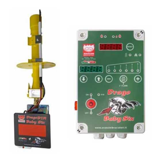
Page 60: Drago Baby Six Control Panel
Instructions, use and maintenance manual 6.1. DRAGO BABY SIX CONTROL PANEL All burner functions can be managed through the use of the Drago BABY SIX panel, as you can see below. Page 60... - Page 61 Instructions, use and maintenance manual POS. ICON/BUTTON DESCRIPTION Burner on switch. tton to increase high ame power. tton to decrease high ame power. Button to increase the set temperature. ress to man ally t rn off and on the ame. Button to decrease the set temperature.
-
Page 62: First Ignition And Adjustment
Instructions, use and maintenance manual 6.2. FIRST IGNITION AND ADJUSTMENT Prior to switching on the burner, make sure the oven loading door is open. CAUTION! efore starting the first ignition, chec the type of gas sed, indicated on the plate and, if required, proceed with the burner conversion, as described in paragraph 7.5. -
Page 63: Celsius / Fahrenheit Degrees Unit Of Measurement Change
Instructions, use and maintenance manual 6.2.1. CELSIUS / FAHRENHEIT DEGREES UNIT OF MEASUREMENT CHANGE To change the unit of measurement of degrees proceed as follows: STEP ACTION PICTURE Disconnect the voltage to the control unit from the main switch inside the room. nscrew the screws to open the rago aby i control panel. -
Page 64: First Ignition With The Controls Of The Control Panel Of The Drago Baby Six
Instructions, use and maintenance manual 6.2.2. FIRST IGNITION WITH THE CONTROLS OF THE CONTROL PANEL OF THE DRAGO BABY SIX IMPORTANT! Open the oven loading door prior to switching on the burner. FIRST IGNITION he proced re for the first ignition is as follows STEP ACTION PICTURE... - Page 65 If the problem persists, vent the gas pipe and then repeat the unlock procedure. If the problem is not solved, contact the technical service of AVANZINI I s.r.l. appears on the green display read o t of set temperat re .
-
Page 66: Cooking Temperature Setting
Instructions, use and maintenance manual 6.2.3. COOKING TEMPERATURE SETTING CAUTION! THE COOKING TEMPERATURE SET IS THE SAME AS THE OVEN OPERATING TEMPERATURE. STEP ACTION PICTURE Press the temperature up button until the temperature to be set shows on the green display. Note: it is rarely necessary to exceed 360°C as set temperature. -
Page 67: Low Flame Gas Adjustment
Instructions, use and maintenance manual 6.2.4. LOW FLAME GAS ADJUSTMENT he low ame is always on when the b rner is wor ing, and has only two f nctions • cook pizzas in a preheated oven, • light up the inside of the baking chamber. he low ame have to heat p the oven, as it is a maintenance ame. - Page 68 Instructions, use and maintenance manual STEP ACTION PICTURE et the ad stment screw in the first sef l position in which the oven T° does not increase, then proceed to adjust the primary air in order to obtain ideal lighting. Position the casing that protects the burner and screw in screw “A”...
-
Page 69: Air Adjustment
Instructions, use and maintenance manual 6.2.5. AIR ADJUSTMENT Primary air is not only subject to the adjustment of the gate, but also to the chimney draught and the gas pressure. Locate the primary air regulator at the base of the torch. The sticker features a series of numerical notches that are merely indicative;... -
Page 70: Gas Parameters
Instructions, use and maintenance manual 6.2.6. GAS PARAMETERS Below is a list of recommended regulation parameters depending on the gas present in the system: GAS TYPE PRESS. POS. METHANE / NATURAL GAS 20 mbar 2 - 4 GPL / LPG 30 mbar 4 - 6 NATURAL GAS... -
Page 71: Setting The Limit Temperature
Instructions, use and maintenance manual 6.2.7. SETTING THE LIMIT TEMPERATURE he limit temperat re is a set val e of ma im m temperat re that, when reached and meas red inside the over, completely shuts off the burner. CAUTION! The safety temperature is factory set at 400°C. -
Page 72: Burner Operation With The Drago Baby Six Control Panel
Instructions, use and maintenance manual 6.2.8. BURNER OPERATION WITH THE DRAGO BABY SIX CONTROL PANEL Programmed temperature shown on the green display matches the oven operating temperature. When the oven internal temperat re shown on the red display drops ntil it reaches less compared to the set temperat re, high ame switches on a tomatically and stays on ntil the temperat re set on the green display is reached once again. -
Page 73: High Flame Power Adjustment
Instructions, use and maintenance manual 6.2.10. HIGH FLAME POWER ADJUSTMENT he high ame can be man ally ad sted in power positions, by pressing the b ttons on the control panel his ad stment is designed to lower the high ame power d ring prod ct coo ing, in order to prevent the pper part from burning. -
Page 74: Switching The Burner Off Via Drago Baby Six
Instructions, use and maintenance manual 6.2.11. SWITCHING THE BURNER OFF VIA DRAGO BABY SIX he following proced re is sed to switch off the b rner from the rago aby i control panel STEP ACTION PICTURE Press the red “ON/OFF” button. he low and the high ame, if ignited, are switched off a tomatically by switching off the burned the green display shows “OFF”... -
Page 75: Error Messages
Instructions, use and maintenance manual 6.3. ERROR MESSAGES 6.3.1. GREEN DISPLAY ERROR MESSAGES COMMUNICATION PICTURE ERR : problem with the burner HUOL : high voltage LUOL : low voltage BLOC : burner locked AL01: probe fault AL02: control panel fault ow ame off OFF LINE: phase and neutral reversed 6.3.2. - Page 76 Instructions, use and maintenance manual Page 76...
-
Page 77: Maintenance
Instructions, use and maintenance manual 7. MAINTENANCE 7.1. INTRODUCTION CAUTION! he maintenance operations m st be carried o t by alified and a thorised personnel. Burner maintenance includes activities (inspection, check, adjustment and replacement) that become necessary following reg lar se of the b rner. For proper maintenance operations: •... -
Page 78: Safety Warnings
Instructions, use and maintenance manual 7.2. SAFETY WARNINGS CAUTION! or the maintenance activities, close the gas s pply system. • aintenance operators are re ired to wear all of the personal protective e ipment gloves, goggles necessary to perform the operation. •... -
Page 79: Routine Maintenance
Instructions, use and maintenance manual 7.3. ROUTINE MAINTENANCE When the burner is delivered to the user, it is already adjusted for correct operation; nonetheless, to ensure good operation over time, it is necessary to carry o t chec s as well as periodic and preventive maintenance. Routine maintenance includes inspections, checks and interventions that, in order to prevent faults, monitor: •... -
Page 80: Machine Cleaning
Instructions, use and maintenance manual 7.3.2. MACHINE CLEANING CAUTION! Before starting any cleaning operation on the machine, isolate and padlock all energy sources and safely loc the mobile nits composing it. ffi the sign achine being serviced do not power near the main switch. -
Page 81: Special Maintenance
Instructions, use and maintenance manual 7.4. SPECIAL MAINTENANCE CAUTION! traordinary maintenance and repair of the machine are only allowed by alified, trained and a thorised technicians, employed by the an fact rer or by the a thorised service centre. These procedures require a thorough and specialist knowledge of equipment, necessary operations, related ris s and correct proced res to wor safely. -
Page 82: Burner Gas Conversion
Instructions, use and maintenance manual 7.5. BURNER GAS CONVERSION CAUTION! The conversion operation requires the purchase of the special conversion kit, which contains a no le and a ame arrestor caps contact I s.r.l. to obtain all information on how to purchase the conversion kit; 7.5.1. - Page 83 Instructions, use and maintenance manual CHARACTERISTICS OF ALTERNATIVE NOZZLES GAS PRESSURE: mbar • with burner on, minimum 13 mbar, maximum 20 mbar; o le diameter . millimetres • with burner off, minimum 17 mbar, maximum 23 mbar; GAS PRESSURE: NOZZLE FOR GPL/LPG 30 mbar: •...
-
Page 84: Nozzle Composition
Instructions, use and maintenance manual 7.5.2. NOZZLE COMPOSITION elow are the main components of the no les POS. DESCRIPTION o le. NOTE:the no le can be replaced as needed. rass no le holder st d bolt. NOTE: the stud bolt must NOT be replaced. Page 84... -
Page 85: Drago Baby Six Control Panel Gas Conversion
Instructions, use and maintenance manual 7.5.3. DRAGO BABY SIX CONTROL PANEL GAS CONVERSION For the conversion procedure based on the type of gas used, proceed as follows: STEP ACTION PICTURE Unscrew the 4 “A” screws to open the Drago aby i control panel. On the back of the control panel identify the “B”... -
Page 86: Flame Arrestor Replacement
Instructions, use and maintenance manual 7.5.4. FLAME ARRESTOR REPLACEMENT or the ame arrestors replacement proced re, carry o t the operations described below STEP ACTION PICTURE oosen the screws of fi ing plates without removing them, using a cross-head screwdriver. Rotate the electrode “B”... -
Page 87: Flame Arrestors
Instructions, use and maintenance manual 7.5.5. FLAME ARRESTORS elow please find the different types of ame arrestors TYPE PICTURE NATURAL GAS Page 87... -
Page 88: Replacing The Burner Sit Control Unit
Instructions, use and maintenance manual 7.5.6. REPLACING THE BURNER SIT CONTROL UNIT DISASSEMBLY For thedisassembly procedure of the burner SIT control unit, carry out the operations described below: STEP ACTION PICTURE emove the lid isconnect connector from the control nit. ndo the screw Page 88... - Page 89 Instructions, use and maintenance manual STEP ACTION PICTURE ndo the screw emove the lid isconnect the connector isconnect the connector Remove the control unit “A” and replace it with one with the same feat res. Page 89...
- Page 90 Instructions, use and maintenance manual ERRORS For the assembly procedure of the burner SIT control unit, follow the operations described here below: STEP ACTION PICTURE osition the control nit onnect the connector onnect the connector Arrange the cables “D” in the special compartment.
- Page 91 Instructions, use and maintenance manual STEP ACTION PICTURE ighten the screw ighten the screw onnect the connector to the control nit, inserting it in terminal “I” osition lid Page 91...
-
Page 92: Probe Replacement
Instructions, use and maintenance manual 7.5.7. PROBE REPLACEMENT For the probe replacement procedure, carry out the operations described below: STEP ACTION PICTURE he green display will show he red display will show eplace the probe. emove and restore power s pply to the control nit disconnecting the pl g. Press the “ON/OFF”... -
Page 93: Troubleshooting
Instructions, use and maintenance manual 8. TROUBLESHOOTING 8.1. INTRODUCTION CAUTION! ALL TROUBLESHOOTING OPERATIONS MUST BE CARRIED OUT WITH THE BURNER SWITCHED OFF. PROBLEM CAUSE SOLUTION DRAGO BABY SIX CONTROL PANEL • Turn on the main switch. DOES NOT SWITCH Main switch off. •... - Page 94 Instructions, use and maintenance manual PROBLEM CAUSE SOLUTION • Check that all the gas system valves between the burner and counter are open, including the safety solenoid valves. Disassemble the burner and: DRAGO BABY SIX CONTROL PANEL • Clean it: turn it over and, if necessary, blow compressed air TURNS ON, THE from the air inta e and ame brea er.
- Page 95 Instructions, use and maintenance manual PROBLEM CAUSE SOLUTION hec whether the high ame is on off. If it is on: • Access under the oven, near the SIT control unit. Locate the pl g made p of a female soc et fi ed to the valve body and a male pl g, mobile, fi ed by cable to the drago control THE DRAGO BABY panel.
- Page 96 Instructions, use and maintenance manual PROBLEM CAUSE SOLUTION • 4 lines appear on the red display To replace the probe it is always necessary to disconnect the current (by switching off the main switch and disconnecting the pl g , replace it and connect the c rrent to the entire system again.
- Page 97 Instructions, use and maintenance manual PROBLEM CAUSE SOLUTION hec if high ame is on, otherwise • make sure that the button is NOT lit up in the OFF position. SLOWER HEATING • if the button is off b t high ame does not t rn on, THAN THE NORMAL PARAMETERS: check that the T°...
- Page 98 Instructions, use and maintenance manual PROBLEM CAUSE SOLUTION RED DISPLAY (T° oo ing inside the oven, yo see a single ame on too high INSIDE THE OVEN) • Locate F1 under the oven EXCEEDS THE • nscrew the brass cover with a at head screwdriver GREEN DISPLAY •...
-
Page 99: Error Messages
Instructions, use and maintenance manual 8.2. ERROR MESSAGES DISPLAY CAUSE SOLUTION • Check that the multipolar plug of the Drago Baby Six control panel is correctly inserted in the socket in the burner; • Disassemble and blow the burner and its air vents; Problem with the •... -
Page 100: Manufacturer's Advice
Instructions, use and maintenance manual 8.3. MANUFACTURER’S ADVICE COMBINED USE OF WOOD + GAS With this solution the traditional wood-burning aspect is maintained; wood does not change either the taste or the smell of the product • no plug • partition between wood and burner: brick laid on its side •... -
Page 101: Attachments
The enclosed documentation constitutes an integral part of the "INSTRUCTIONS, USE AND MAINTENANCE MANUAL" of the machine supplied by AVANZINI BRUCIATORI s.r.l.. It must be used as a reference for the use, operation and maintenance of the equipment and components. -
Page 102: Burner Control Unit Diagram
Instructions, use and maintenance manual 9.1. BURNER CONTROL UNIT DIAGRAM LAMPADA RESET BLOCCO CONTATTO EV. 2 FIAMMA Page 102... -
Page 103: Connections Diagram
Instructions, use and maintenance manual 9.2. CONNECTIONS DIAGRAM 5-POLE PLUG (WHITE) DESCRIPTION IDENTIFICATION - Controls - Modulating valve positive Modulating valve negative Solenoid valve no.2 Brown Phase from SIT control unit SV2 Black power supply Reset White 4-POLE PLUG (BLACK) DESCRIPTION IDENTIFICATION - Power supply -... - Page 104 AVANZINI BRUCIATORI s.r.l. Via G. Battistini, 11 43122 - Parma -(Pr) Italy tel. +39 0521 271344 fax +39 0521 775862 info@avanzinibruciatori.it Updated on: 07/2018...
Need help?
Do you have a question about the DRAGO D1/M and is the answer not in the manual?
Questions and answers