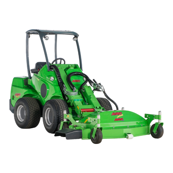
Lawn Mower 1500 2018 1 CONTENTS 1. FOREWORD ............................4 Warning symbols used in this manual ..........................5 2. DESIGNED PURPOSE OF USE ......................6 3. SAFETY INSTRUCTIONS FOR USING THE ATTACHMENT ............7 4. TECHNICAL SPECIFICATIONS ......................10 Safety labels and main components of the attachment.................. 11 5.
If you sell or transfer the equipment, be sure to hand over this manual to the new owner. If the manual is lost or damaged, you can request a new one from your Avant dealer or from the manufacturer.
5 (32) Warning symbols used in this manual The following warning symbols are used throughout this manual. They indicate factors that must be taken into account to reduce the risk of personal injury or damage to property: WARNING: SAFETY ALERT SYMBOL This symbol means: “Warning, be alert! Your safety is involved!”...
2. Designed purpose of use The AVANT Lawn mower 1500 is an attachment suitable for use with AVANT multi purpose loaders shown in Table 1. The lawn mower is suitable for residential and professional use as well. It is intended to be used to move lawns on level, tended areas free of rocks, tree stumps, large branches, or other similar obstacles.
7 (32) 3. Safety instructions for using the attachment Please bear in mind that safety is the result of several factors. The loader-attachment combination is highly powerful and improper or careless use or maintenance may cause serious personal injury or property damage.
Page 8
8 (32) Be sure not to tilt the lawn mower too far up, since this will make it tip over towards the loader boom due to the movement made possible by the floating system linkage. Secure the mower against unintended movements when unlocking it from the loader. Unlock only on a level surface, and use blocks of wood to prevent the mower from WARNING moving, for example.
Page 9
9 (32) Risk of crushing - Never allow anyone to get under a lifted attachment or loader boom. Keep in mind that the loader boom can be lowered or tilted even if the engine has WARNING been shut down (crushing hazard). The loader is not intended to be left to keep a load elevated for longer periods.
45-55 l/min Maximum input of hydraulic energy: 22,5 MPa (225 bar), 65 l/min Compatible Avant loaders: See Table 1 Choose a mower that is compatible with the loader. Do not exceed the maximum input of hydraulic energy or the operating pressure.
11 (32) 4.1 Safety labels and main components of the attachment Listed below are the labels and markings on the attachment. They must be visible and readable on the equipment. Replace any unclear or missing label. New labels are available via your retailer or contact information provided on the cover.
Page 12
12 (32) Table 3 - Decal locations and warning messages Decal Warning message A46771 Misuse hazard - Read instructions before use. A46772 Crushing hazard - Do not go under a raised attachment; stay away from raised equipment. A46798 Risk of getting drawn into and crushed by belt drive components;...
Do not stay in the area between the attachment and the loader. Mount the attachment only on level surface. WARNING Never move or lift an attachment that has not been locked. Avant quick coupling system: Step 1: Lift the quick attach plate locking pins up and turn them backwards into the slot so that they are locked in the upper position.
5.1 Connecting and disconnecting hydraulic hoses On Avant loaders the hydraulic hoses are connected using the multi connector system. If you have an Avant 300-700 series loader with the conventional quick couplers and wish to change to the multi connector system, contact your Avant dealer or service point for instructions or installation services.
Page 15
15 (32) Keep all fittings as clean as possible; use the protective caps on both the attachment and the loader. Dirt, ice, etc. may make using the fittings significantly more difficult. Never leave the hoses hanging on the ground; place the couplings onto the holder on the attachment.
16 (32) 6. Instructions for use Check the attachment and the operating environment once more before starting to work, and that all obstacles have been removed from the operating area. Quick inspection of the equipment and the operating area before use are parts of ensuring safety and the best performance of the equipment.
17 (32) 6.1 Checks before use Remove or mark visibly all obstacles, such as trash, large tree branches or stones, from the working area before operation. Check the area for possible hidden ditches, manholes, or other dangerous areas. Remember that tall grass can hide obstacles. Set and lock all four wheels of the mower to same height.
18 (32) 6.2 Using the mower Set and adjust the mower to correct operating position before starting the mower. See following chapters about floating system and adjustments. Starting the mower: Move the auxiliary hydraulics control lever of the loader towards its locking position (or use electric buttons on joystick, if equipped) to operate the mower.
Page 19
19 (32) Recommended operating speed and maximum allowed oil flow: Adjust engine RPM so that the loader's auxiliary hydraulic flow is within the specified range for the mower. Too little flow will not rotate the blades fast enough for good mowing results. Correct flow ensures that the blades to rotate fast enough for a good finish.
20 (32) 6.3 Working on uneven ground Extra caution is needed when using the equipment on inclined terrains and slopes. Drive slowly especially on inclined, uneven, or slippery surfaces, and avoid sudden changes in speed or direction. Operate the controls of the loader with careful and smooth movements.
21 (32) 6.6 OptiFloat® The attachment is equipped with a mechanical floating system, which enables efficient operation on uneven terrains. Floating refers to a linkage that allows the attachment to follow the contours of the ground surface without moving the loader boom. OptiFloat® allows the attachment to tilt sideways as well and eliminates the need for floating of the loader boom.
22 (32) 6.6.1 Safety valve For safety, the attachment is equipped with a valve that prevents using the attachment when it has been lifted off the ground. The valve stops the hydraulic flow to the hydraulic motor of the attachment when the attachment is raised or when the floating has been set too low.
23 (32) 6.8 Handling of the clippings If necessary, the lawn mower can be fitted with mulching kit A34530 to allow leaving clippings evenly under the mower. Either the parts related to the side discharge mode or the mulching mode must be installed. Operating mode How to use Side discharge Standard setting - Side discharge chute must be installed...
24 (32) 6.8.1 Installing side discharge chute To fit the side discharge chute, install the bracket, pin, and the spring first: Hazard of thrown objects and cutting. Make sure the side discharge chute is intact and properly fastened. The chute must be removed only when the mulching kit is installed. WARNING 6.8.2 Mulching kit A34530...
25 (32) 6.9 Removing a blockage It is unlikely that the cutting deck gets blocked in normal operation. However, when mowing wet grass or driving at too high speed, the side discharge chute may get blocked. If blocking occurs, also check the cutting deck and clean if necessary.
Finding any fault means that the hydraulic hose or component must be replaced and the equipment must not be used until it is repaired. Spare parts are available from your nearest AVANT retailer or authorised service point. Leave the repair work to professional service technicians, if you don’t have adequate knowledge and experience about hydraulic assemblies and how to perform the repairing safely.
27 (32) 7.2 Cleaning and lubricating the mower Drying grass may build up to decrease the performance of the mower and should be removed after each use. The mower deck should only be cleaned manually to avoid damaging the bearings. Stop the loader and disconnect hydraulic couplings, then remove grass by using a stick or brush.
28 (32) Risk of ejected parts - Make sure that all blades are connected securely. Check that all blades are connected securely and that none of the blades is missing. Loose, damaged, or missing blades can cause ejection of parts from the mower. Only use WARNING locking nuts for fastening the blades.
29 (32) 7.4 Checking and tightening the belt The tightness and the condition of the drive belt must be checked at least annually at the beginning of each mowing season, and depending on use, a few times during the season. A belt that is not at its correct tightness may not necessarily be apparent to the user, but sudden slipping or breaking of the belt may lead to hazardous situation or damage to the mower or the blades.
30 (32) 8. Warranty terms Avant Tecno Oy grants a warranty of one year (12 months) from the date of purchase for the attachment it manufactures. The warranty covers repair costs as follows: Work costs are covered, if the repair is not performed at the factory.
Page 31
SFS-EN ISO 12100, SFS-EN ISO 4413 Mallit / Modeller / Models: Avant Hydraulitoiminen ruohonleikkuri; Avant-kuormaajan työlaite Hydraulisk gräsklippare; arbetsredskap för Avant lastare A37548 Hydraulic lawn mower; attachment for Avant loaders 22.12.2017 Ylöjärvi, Finland Risto Käkelä, Toimitusjohtaja / Verkställande direktör / Managing Director Original language version...
Need help?
Do you have a question about the I500 and is the answer not in the manual?
Questions and answers