DEWESOFT DS-VGPS-HS Technical Reference Manual
Hide thumbs
Also See for DS-VGPS-HS:
- Technical reference manual (29 pages) ,
- Soft user manual (46 pages)
Table of Contents
Advertisement
Quick Links
Advertisement
Table of Contents

Related Manuals for DEWESOFT DS-VGPS-HS


Summary of Contents for DEWESOFT DS-VGPS-HS
- Page 1 DS-VGPS-HS TECHNICAL REFERENCE MANUAL DS-VGPS-HS V21-1...
-
Page 2: Table Of Contents
5.2. Options 5.2.1. Brake trigger switch 5.2.2. Digital display 6. Installation of the DEWESoft X measurement software 6.1. Installation of the DS-VGPS-HS 6.2. Configuration of DEWESoft X for the DS-VGPS-HS 6.3. Channel setup 6.4. Measurement 6.5. Analysis 7. Warranty information 7.1. - Page 3 TECHNICAL REFERENCE MANUAL 8.1. Safety symbols in the manual 8.2. General Safety Instructions 8.2.1. Environmental Considerations 8.2.2. Product End-of-Life Handling 8.2.3. System and Components Recycling 8.2.4. General safety and hazard warnings for all Dewesoft systems 9. Documentation version history V21-1 3/30...
-
Page 4: About This Document
DS-VGPS-HS TECHNICAL REFERENCE MANUAL 2. About this document 2.1. Legend The following symbols and formats will be used throughout the document. Important It gives you important information about the subject. Please read carefully! Hint It gives you a hint or provides additional information about a subject. -
Page 5: Gps Based System For Position, Speed And Displacement Measurement
Supports differential GPS (SBAS) as standard function ● Mark input for brake trigger switch ● Data over USB or COM with zero latency PPS sync ● Image 1: DS-VGPS-HS 3.2. Options Brake trigger switch ● High bright display ● RTK-2 with 20 Hz or 100 Hz with L1/L2 and Glonass (all Rover and Base modes) ●... -
Page 6: Specifications
DS-VGPS-HS TECHNICAL REFERENCE MANUAL 3.3. Specifications DS-VGPS-HS/HSC NAVIGATION Standalone (horizontal positioning) 1.2 m Standalone (vertical positioning) 1.8 m SBAS (horizontal positioning) 0.8 m (WAAS, EGNOS 0.3 m) SBAS (vertical positioning) 1.2 m (WAAS, EGNOS 0.5 m) Omnistar (horizontal positioning) *... -
Page 7: Device Overview
Orientation of different object 3.4. Device overview With the DS-VGPS-HS, DewesoftX® offers the latest 100 Hz technology of GPS based speed and displacement sensors. The result of this highest dynamic GPS receiver is the most easy to use speed/distance sensor with that bandwidth. In addition to this no calibration drives for different road conditions (ice, water, snow, off road) are needed. -
Page 8: Mounting The Aerial
DS-VGPS-HS TECHNICAL REFERENCE MANUAL Beside the filter characteristic of the internal algorithm, the latency time on the serial interface is related to the basic structure of any GPS-based sensor. After acquiring the GPS raw data, the time consuming calculation to get the position and speed and the data transfer time will delay the data from the DS-VGPS-HS. -
Page 9: Warm-Up Time
DS-VGPS-HS TECHNICAL REFERENCE MANUAL Image 3: Antenna mount 3.6. Warm-Up time When the VGPS is used for the first time, has been moved more than 200 km or not used for 10 hours (since last usage), it is recommended to perform a ‘cold start’. To get the best performance from your VGPS in the future, perform this cold start in an open place with a good all round view to the sky. -
Page 10: Scope Of Supply
DS-VGPS-HS TECHNICAL REFERENCE MANUAL 4. Scope of supply Image 4: Scope of supply V21-1 10/30... -
Page 11: Connection
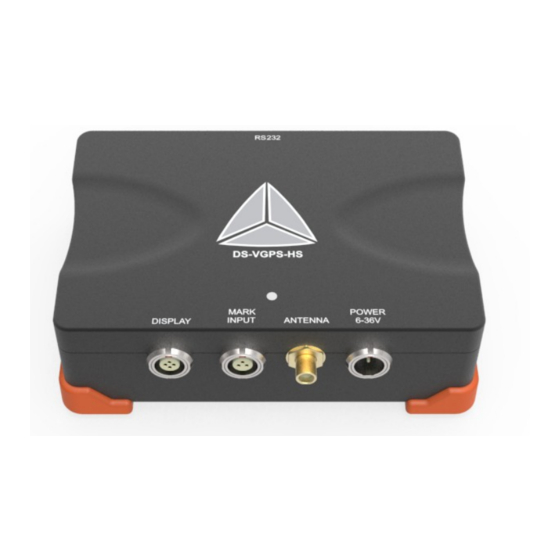
DS-VGPS-HS TECHNICAL REFERENCE MANUAL 5. Connection 5.1. Connector overview Image 5: Inputs 5.1.1. Aerial connector Connect the GPS aerial to the SMA connector. Image 6: SMA connector V21-1 11/30... -
Page 12: Rs-232 Interface
GND (Ground) PPS (pulse per second) Image 7: RS-232 connector (DSUB-9 female) Not connected Not connected Not connected 5.1.3. VGPS – Display connector To connect the external display to the DS-VGPS-HS system. Description Image 8: VGPS display connector EXG.1B.304.HLN V21-1 12/30... -
Page 13: Mark Input Connector
Signal Image 9: Mark input connector: pin-out (3-pin LEMO female) EXG-1B.303.HLN 5.1.5. Power supply connector Connects the DS-VGPS-HS system to an external DC power supply. Description +9 to +36 VDC power supply GND power supply Image 10: Power supply connector (2-pin LEMO male) EXJ.1B.302.HLD... -
Page 14: Cable For External Power Supply
DS-VGPS-HS TECHNICAL REFERENCE MANUAL 5.1.6. Cable for external power supply Type of cable: LIYY 2x0.75, length: 2 m Standard: (included) Optional: Optional: Image 11: External power supply Optional: AC adapter + different AC cable (depends on the country) Image 12: Power supply... -
Page 15: Cable For Connecting Vgps To Vgps-Display (Optional)
DS-VGPS-HS TECHNICAL REFERENCE MANUAL 5.1.7. Cable for connecting VGPS to VGPS-Display (optional) Type of cable: LIYCY 4x0.25 shielded, length: 2 m Image 13: VGPS display cable Image 15: FGJ.1B.304.CLLD52Z Image 14: FGJ.1B.304.CLAD52Z V21-1 15/30... -
Page 16: Options
This switch can be connected directly to an input of the data acquisition system or to the DS-VGPS-HS. The DS-VGPS-HS will recognize the exact time of the switching point. A serial command with this time information will be transmitted to the data acquisition unit. - Page 17 DS-VGPS-HS TECHNICAL REFERENCE MANUAL Mode 01: Number of satellites and velocity in mph. Mode 02: Number of satellites and velocity in kph. Mode 03: GPS UTC time reported by the satellites goes up in increments of 0.05 seconds. The format is hh.mm.ss.
-
Page 18: Installation Of The Dewesoft X Measurement Software
DS-VGPS-HS TECHNICAL REFERENCE MANUAL Mode 05: Number of satellites and height relative to the Datum WGS84 (approx. 50 meters below UK sea level). Resolution: 0.1 meters 6. Installation of the DewesoftX® measurement software For optimal operation, we recommend that you install the latest version of DewesoftX® . If you already have DewesoftX®... -
Page 19: Installation Of The Ds-Vgps-Hs
Image 18: Settings GPS device A list of the supported GPS systems. Select the Dewesoft RS232 (Topcon/Javad/NVS) GPS device. If it doesn't find the Model of receiver press the Refresh button or you have to switch COM port. COM port Select the corresponding COM port in the drop down menu. - Page 20 Serial number of the connected GPS sensor. Serial number is recorded to reconstruct the measurement conditions. Receiver dynamic settings Depending on the application, the DS-VGPS-HS offers the possibility to set it into three different settings. These can be done in the pull down menu Receiver dynamic settings.
-
Page 21: Channel Setup
When you are finished in the hardware settings, click on the ‘Ch. setup’ button and select ‘GPS’. Image 19: Channel setup The screenshot below shows the channel setup screen of the DS-VGPS-HS. In the column ON/OFF you can select the channels for storing during the measurement. The default channel names are displayed in the column NAME. -
Page 22: Measurement
DS-VGPS-HS TECHNICAL REFERENCE MANUAL Used satellites: Numbers of satellites used for calculation of position and speed ● Current sec: This channel counts the seconds since midnight UTC ● Mark input: Indicates an event at the mark input by changing the level from 0 to 1 ●... -
Page 23: Analysis
DS-VGPS-HS TECHNICAL REFERENCE MANUAL Image 22: GPS screen 6.5. Analysis After measurement you can analyze the stored data. One click on the “Analysis“ button gives you the possibility to choose a recorded data file and analyze it. Image 23: Analysis Use the cursor functions to zoom in/out, cut out and print out. -
Page 24: Warranty Information
7.2. Support Dewesoft has a team of people ready to assist you if you have any questions or any technical difficulties regarding the system. For any support please contact your local distributor first or Dewesoft directly. -
Page 25: Printing History
When used in text representing the company, product or technology name, the ® sign is not used. The Dewesoft triangle logo is a registered trademark but the ® sign is not used in the visual representation of the triangle logo. -
Page 26: Safety Instructions
Dewesoft GmbH assumes no liability for the customer’s failure to comply with these requirements. All accessories shown in this document are available as an option and will not be shipped as standard parts. -
Page 27: General Safety And Hazard Warnings For All Dewesoft Systems
REMOVE POWER and do not use the product until the safe operation can be verified by service-trained personnel. If necessary, return the product to Dewesoft sales and service office for service and repair to ensure that safety features are maintained. - Page 28 DS-VGPS-HS TECHNICAL REFERENCE MANUAL noises. the system does not work anymore. The system has been exposed to long storage in adverse environments. the system has been exposed to heavy shipment strain. Warranty void if damages caused by disregarding this manual. For consequential damages, NO ●...
- Page 29 DS-VGPS-HS TECHNICAL REFERENCE MANUAL IEC 61326-1 applies to this part of IEC 61326 but is limited to systems and equipment for industrial applications intended to perform safety functions as defined in IEC 61508 with SIL 1-3. The electromagnetic environments encompassed by this product family standard are industrial, both indoor and outdoor, as described for industrial locations in IEC 61000-6-2 or defined in 3.7 of IEC 61326-1.
-
Page 30: Documentation Version History
DS-VGPS-HS TECHNICAL REFERENCE MANUAL 9. Documentation version history Revision number: 32 Last modified: Tue 25 Feb 2014, 16:04 Version Date Notes 1.0.0 22-02-2014 ☑ initial revision V20-1 25-09-2020 Template update V20-2 12-10-2020 Updated renders V21-1 23-02-2021 Corrected template styling V21-1...
Need help?
Do you have a question about the DS-VGPS-HS and is the answer not in the manual?
Questions and answers