DEWESOFT DS-VGPS-HS Technical Reference Manual
Hide thumbs
Also See for DS-VGPS-HS:
- Soft user manual (46 pages) ,
- Technical reference manual (30 pages)
Table of Contents
Advertisement
Quick Links
Advertisement
Table of Contents

Related Manuals for DEWESOFT DS-VGPS-HS


Summary of Contents for DEWESOFT DS-VGPS-HS
- Page 1 DS-VGPS-HS TECHNICAL REFERENCE MANUAL DS-VGPS-HS V20-2 1 ...
-
Page 2: Table Of Contents
5.2.1. Brake trigger switch 15 5.2.2. Digital display 16 6. Installation of the DEWESoft X measurement software 18 6.1. Installation of the DS-VGPS-HS 20 6.2. Configuration of DEWESoft X for the DS-VGPS-HS 20 6.3. Channel setup 23 6.4. Measurement 25 6.5. Analysis 26 ... - Page 3 8.2. General Safety Instructions 30 8.2.1. Environmental Considerations 30 8.2.2. Product End-of-Life Handling 30 8.2.3. System and Components Recycling 30 8.2.4. General safety and hazard warnings for all Dewesoft systems 31 9. Documentation version history 34 DS-VGPS-HS V20-2...
-
Page 4: About This Document
It gives you important information about the subject. Please read carefully! Hint It gives you a hint or provides additional information about a subject. Example Gives you an example of a specific subject. DS-VGPS-HS V20-2 4/29 ... -
Page 5: Gps Based System For Position, Speed And Displacement Measurement
● Data over USB or COM with zero latency PPS sync ● Image 1: DS-VGPS-HS 3.2. Options Brake trigger switch ● High bright display ● RTK-2 with 20 Hz or 100 Hz with L1/L2 and Glonass (all Rover and Base modes) ... -
Page 6: Specifications
ADDITIONAL FEATURES PPS output ✓ IRIG B DC output Dual antenna heading RTK positioning ✓ HARDWARE Interface RS232 / USB, CAN, Analog, Digital Operating voltage 9 to 36 V Power consumption 250 mA @ 12 V DS-VGPS-HS V20-2 6/29 ... -
Page 7: Device Overview
Orientation of different object 3.4. Device overview With the DS-VGPS-HS, DewesoftX® offers the latest 100 Hz technology of GPS based speed and displacement sensors. The result of this highest dynamic GPS receiver is the most easy to use speed/distance sensor with that bandwidth. In addition to this no calibration drives for different road ... -
Page 8: Mounting The Aerial
VGPS can work with at least three satellites, it's precision increases the more satellites it finds. If one satellite disappears over the horizon, or behind an object, there are other satellites still in view. Image 3: Antenna mount DS-VGPS-HS V20-2 8/29 ... -
Page 9: Warm-Up Time
15 seconds and 1 minute. Before going to test in a shady environment with tall objects or near to trees, allow the VGPS to settle in an open space for 5 to 10 minutes. 4. Scope of supply Image 4: Scope of supply DS-VGPS-HS V20-2 9/29 ... -
Page 10: Connection
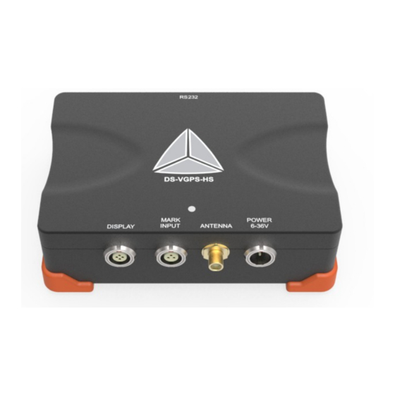
DS-VGPS-HS TECHNICAL REFERENCE MANUAL 5. Connection 5.1. Connector overview Image 5: Inputs 5.1.1. Aerial connector Connect the GPS aerial to the SMA connector. Image 6: SMA connector DS-VGPS-HS V20-2 10/29 ... -
Page 11: Rs-232 Interface
Image 7: RS-232 connector (DSUB-9 female) 7 Not connected 8 Not connected 9 Not connected 5.1.3. VGPS – Display connector To connect the external display to the DS-VGPS-HS system. Pin Description 1 +5V 2 GND 3 TXD ... -
Page 12: Mark Input Connector
3 Signal Image 9: Mark input connector: pin-out (3-pin LEMO female) EXG-1B.303.HLN 5.1.5. Power supply connector Connects the DS-VGPS-HS system to an external DC power supply. Pin Description 1 +9 to +36 VDC power supply 2 ... -
Page 13: Cable For External Power Supply
Optional: Optional: Image 11: External power supply Optional : AC adapter + different AC cable (depends on the country) Image 12: Power supply DS-VGPS-HS V20-2 13/29 ... -
Page 14: Cable For Connecting Vgps To Vgps-Display (Optional)
5.1.7. Cable for connecting VGPS to VGPS-Display (optional) Type of cable: LIYCY 4x0.25 shielded, length: 2 m Image 13: VGPS display cable Image 15: FGJ.1B.304.CLLD52Z Image 14: FGJ.1B.304.CLAD52Z DS-VGPS-HS V20-2 14/29 ... -
Page 15: Options
This switch can be connected directly to an input of the data acquisition system or to the DS-VGPS-HS. The DS-VGPS-HS will recognize the exact time of the switching point. A serial command with this time information will be transmitted to the data acquisition ... - Page 16 Coordinate, derived from the atomic clocks on board the satellite and hence is extremely accurate. Mode 04: Heading in degrees. Number of satellites and heading of the vehicle relative to true North. Resolution: 0.1 degree DS-VGPS-HS V20-2 16/29 ...
-
Page 17: Installation Of The Dewesoft X Measurement Software
Support/Downloads/DewesoftX section or directly in software under the Options/Check for updates. In both cases the changelog is included Image 17: Check for updates DS-VGPS-HS V20-2 17/29 ... -
Page 18: Installation Of The Ds-Vgps-Hs
6.1. Installation of the DS-VGPS-HS After installing DewesoftX® , connect the RS-232 connector to the corresponding COM port of your system. Check on which COM port is DS-VGPS-HS connected in the Device manager. 6.2. Configuration of DewesoftX® for the DS-VGPS-HS ... - Page 19 ● ms at the analog and speed output is needed. High ( handling test): Because of the PPS-Sync facility of the DS-VGPS-HS, this setting will not ● increase the latency time and the dynamic behavior using the serial interface for data ...
-
Page 20: Channel Setup
Image 19: Channel setup The screenshot below shows the channel setup screen of the DS-VGPS-HS. In the column O N/OFF you can select the channels for storing during the measurement. The default channel names are displayed in the column N AME . You can change them with a double click on it. Beside the channel names the ... -
Page 21: Measurement
6.4. Measurement Now you are ready for measuring. Clicking the “Measure“ button opens the measurement screen. Image 21: Measure With the “Store“ and “Stop“ button in the recorder you can control the measurement manually. DS-VGPS-HS V20-2 21/29 ... -
Page 22: Analysis
Use the cursor functions to zoom in/out, cut out and print out. With the “Export“ function you can export data to other applications, like Excel, Word etc. Find details about DewesoftX® in the D ewesoftX® Software User's Manual . DS-VGPS-HS V20-2 22/29 ... -
Page 23: Warranty Information
7.2. Support Dewesoft has a team of people ready to assist you if you have any questions or any technical difficulties regarding the system. For any support please contact your local distributor first or Dewesoft directly. ... -
Page 24: Printing History
When used in text representing the company, product or technology name, the ® sign is not used. The Dewesoft triangle logo is a registered trademark but the ® sign is not used in the visual representation of the triangle logo. ... -
Page 25: Safety Instructions
Failure to comply with these precautions or with specific warnings elsewhere in this manual violates safety standards of design, manufacture, and intended use of the product. Dewesoft GmbH assumes no liability for the customer’s failure to comply with these requirements. ... -
Page 26: General Safety And Hazard Warnings For All Dewesoft Systems
REMOVE POWER and do not use the product until the safe operation can be verified by service-trained personnel. If necessary, return the product to Dewesoft sales and service office for service and repair to ensure that safety features are maintained. ... - Page 27 This product has left the factory in safety-related flawlessness and in proper condition. In order to ● maintain this condition and guarantee safety use, the user has to consider the security advice and warnings in this manual. DS-VGPS-HS V20-2 27/29 ...
- Page 28 Devices and systems according to IEC 61508 or IEC 61511 which are considered as “operationally well-tried”, are excluded from the scope of IEC 61326-3-1. Fire-alarm and safety-alarm systems, intended for the protection of buildings, are excluded from the scope of IEC 61326-3-1. DS-VGPS-HS V20-2 28/29 ...
-
Page 29: Documentation Version History
TECHNICAL REFERENCE MANUAL 9. Documentation version history Revision number: 32 Last modified: Tue 25 Feb 2014, 16:04 Version Date [dd.mm.yyyy] Notes 1.0.0 22.02.14 ☑ initial revision V20-1 25.9.2020 Template update V20-2 12.10.2020 Updated renders DS-VGPS-HS V20-2 29/29 ...
Need help?
Do you have a question about the DS-VGPS-HS and is the answer not in the manual?
Questions and answers