Table of Contents
Advertisement
Quick Links
Advertisement
Table of Contents

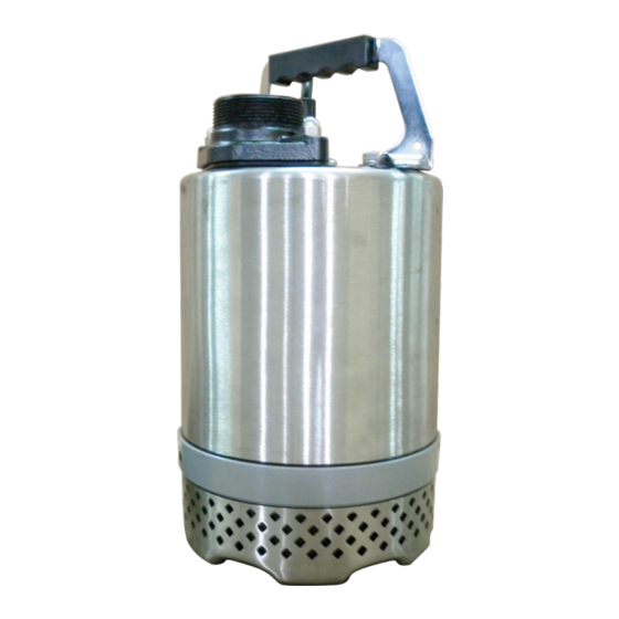
Summary of Contents for Stancor SSD Series
- Page 1 Installation, Operation and Maintenance Manual Stancor™ SSD & SL Series Pumps...
-
Page 2: Table Of Contents
Table of Contents Safety Guidelines Caution Wiring Maintenance Nameplate format Prior to Operation Installation Electrical Wiring Wiring Cable Grounding Wiring Diagrams Operation Maintenance Exploded View (SSD-75&100) List of Parts (SSD-75&100) Exploded View (SL-75&100) List of Parts (SL-75&100) Exploded View (SSD-200) List of Parts (SSD-200) Troubleshooting Disassembly and Assembly... -
Page 3: Safety Guidelines
Safety Guidelines This instruction manual provides you with the information required to safely own and operate your product. Retain these instructions for future reference. The product you have purchased is of the highest quality workmanship and material and has been engineered to give you long and reliable service. -
Page 4: Caution
Pump should be connected or wired to its own circuit with no other outlets or equipment in the circuit line. Fuses and circuit breaker should be of ample capacity in the electrical circuit. Maintenance If the pump does not operate properly or trouble shooting doesn’t work, consult your pump dealer or take pump to a Stancor authorized service center. Nameplate format... -
Page 5: Prior To Operation
Prior to Operation Check the following points upon receipting of your pump: Is the pump exactly what you ordered? Check nameplate. It is especially important that you check whether the pump is to be used with 50 or 60 Hz. Has any damage occurred during shipment? Are any bolts or nuts loose? Have all necessary accessories been supplied? We recommend that you keep a spare pump on hand in case of emergencies. -
Page 6: Electrical Wiring
Electrical Wiring Wiring A) Wire as indicated for the appropriate start system as shown in Fig-3 for single phase version and Fig-4 for three phase. B) Loose connections will stop the pump. Make sure all electrical connections secure. Cable WARNING: Never let the end of the cable contact water. C) If the cable is extended, do not immerse the splice in water. -
Page 7: Operation
Operation 1. Before starting the pump 1. After completing installation, measure the insulation resistance again as described in Installation. 2. Check water level. If the pump is operated continuously for an extended period in a dry condition or at the lowest water level, the motor protector will be shut off the power. -
Page 8: Exploded View (Ssd-75&100)
Exploded View (SSD-75&100) -
Page 9: List Of Parts (Ssd-75&100)
List of Parts (SSD-75&100) Name Mtrl Photo Name Mtrl Photo Protector Cable H07/UL (1 Phase) ptio n al) Protector Handle Steel (3 Phase) Motor ADC12 Capacitor Cover Bracket Steel Bearing Motor Housing ADC12 Strainer SUS 304 +Stator O-ring Shaft with Rotor SUS 410 PA66+20% 18-3... -
Page 10: Exploded View (Sl-75&100)
Exploded View (SL-75&100) -
Page 11: List Of Parts (Sl-75&100)
List of Parts (SL-75&100) Name Mtrl Photo Name Mtrl Photo Protector Cable H07/UL (1 Phase) (Optional) Protector Handle Steel (3 Phase) Motor ADC12 Capacitor Cover Bracket Steel Bearing Motor Housing ADC12 Strainer +Stator Shaft with Rotor O-ring PA66+20% Oil Chamber ADC12 18-3 Wearing Plate... -
Page 12: Exploded View (Ssd-200)
Exploded View (SSD-200) -
Page 13: List Of Parts (Ssd-200)
List of Parts (SSD-200) Name Mtrl Photo Name Mtrl Photo Protector Cable H07/UL (1 Phase) p tio n al) Protector Handle Steel (3 Phase) Motor ADC12 Capacitor Cover Bracket Steel Bearing Motor Housing ADC12 Strainer SUS 304 +Stator Shaft with Rotor SUS 410 O-ring PA66+20%... -
Page 14: Troubleshooting
Troubleshooting Remedy Trouble Cause (1) Power failure Does not start. (1)~(3) Contact electric power company and devise counter-measures Starts, but (2) Large discrepancy between power source and volt- immediately (3) Significant drop in voltage stops. (4) Motor phase malfunction (4) Inspect electric circuit (5) Electric circuit connection faulty (5) Correct wiring (6) Faulty connection of control circuit... -
Page 15: Disassembly And Assembly
Disassembly and Assembly Disassembly- When disassembling pump, have a piece of cardboard or wooden board ready to place the different parts on as you work. Do not pile parts on top of each other. They should be laid out neatly in rows. The “O” ring and gasket cannot be used again once they are removed. -
Page 16: Appendices
Appendices: Technical Data: SSD SSD-75 DS-A13-001 SSD-100 DS-A13-005 SSD-200 DS-A13-009 Specifications: SSD SSD-75 DS-A13-002 SSD-100 DS-A13-006 SSD-200 DS-A13-010 Technical Data: SL SL-75 DS-A12-001 SL-100 DS-A12-005 Specifications: SL SL-75 DS-A12-002 SL-100 DS-A12-006... -
Page 17: Notes
Notes Industrial Flow Solutions Operating, LLC • 104 John W Murphy Drive, New Haven, CT 06513, USA • 860-399-5937 • www.flowsolutions.com Stancor™ is a trademark of Industrial Flow Solutions Operating, LLC. All rights reserved.


Need help?
Do you have a question about the SSD Series and is the answer not in the manual?
Questions and answers