Table of Contents
Advertisement
Quick Links
Advertisement
Table of Contents

Related Manuals for HS-Technik NutBee NBLS-21


Summary of Contents for HS-Technik NutBee NBLS-21
- Page 1 OPERATING INSTRUCTIONS NutBee ® - Original operating instructions - Cordless blind riveting tool NBLS-21 / NBLF-25 NOTE Issue date: February 2021 In case of doubt, the original German version Tool Firmware: from 2.2.6.0 of the operating instructions applies. HST-Tool-Manager: from 2.0.6.0...
-
Page 2: Table Of Contents
Table of contents 1 Operating principles Scope of delivery General information Signs and symbols used Structure of the warnings Technical terms and abbreviations used Intended use Improper use Duties of the operator Duties of personnel 1.10 Training of personnel 1.11 Guarantee and liability 1.12 Copyright... - Page 3 4.2.15 Standby and Shut-down mode 4.2.16 Charge state of the battery 4.2.17 Display notifications HST-Tool-Manager 4.3.1 Setup 4.3.2 General → energy & lighting 4.3.3 General → features 4.3.4 General → TM version 4.3.5 Management 4.3.6 Signals → OLED-display 4.3.7 Signals → LED 4.3.8 Signals →...
-
Page 4: Operating Principles
1 Operating principles Dear customers, thank you for choosing a HS-Technik GmbH product. This quality product „Made in Germany“ fulfils the highest requirements with regard to performance, quality and accuracy. When used correctly the product will undoubtedly perform very well for many years. - Page 5 This operating instructions must be read and applied by every person who is assigned to conduct work using this tool. In addition to this operating instructions the applicable regulations on accident prevention and environmental protection should be observed. NOTE After reading, keep the operating instructions in a place accessible to every operator.
-
Page 6: Signs And Symbols Used
Signs and symbols used The following signs and symbols will be used in this operating instructions or on the product: Symbol Explanation Read this operating instructions Do not dispose with household waste Do not dispose the battery in a fire Do not throw the battery into water EU conformity marking ®... -
Page 7: Structure Of The Warnings
Structure of the warnings The warnings are structured as follows: DANGER Indicates an immediate dangerous situation that can lead to serious or even deadly injuries and/or that could seriously damage or even destroy the tool. WARNING Indicates a potentially dangerous situation that can lead to serious injuries and/or damage to the tool. -
Page 8: Intended Use
• following all indications of the operating instructions and • observance of inspection and maintenance works. Any other use or use beyond that is considered improper use. HS-Technik GmbH is not liable for any damage resulting from this. Improper use DANGER The use of this tool for other purposes, e.g. -
Page 9: Duties Of The Operator
Duties of the operator The operator undertakes to only allow people who are familiar with the basic regulations on occupational safety and accident prevention and who have been trained on how to use the tool at the workplace to work with this tool. The safety awareness of the personnel while working has to reviewed at regular intervals. -
Page 10: Training Of Personnel
1.10 Training of personnel Only trained and instructed personnel should work with this tool. The responsibilities of the personnel must be clearly defined. Trainees may only work with this power tool under the supervision of an experienced person. 1.11 Guarantee and liability Guarantee and liability claims for personal injury and property damage are excluded, if caused by one or more of the following: •... -
Page 11: Copyright
These operating instructions are intended solely for the operator and its personnel. They contain guidelines and information which may not be fully or partially • reproduced • distributed or • otherwise shared. The copyright of these operating instructions is retained by HS-Technik GmbH. Manufacturer’s address: Im Martelacker 12 D-79588 Efringen-Kirchen Telephone:... -
Page 12: General Safety Information For Power Tools
2 General safety information for power tools DANGER Read all the safety information, instructions, illustrations and technical data which is provided with this power tool. Failure to follow the instructions below may result in electric shock, fire and/or serious injury. WARNING This power tool was manufactured in according with current state-of-the-art technology and recognised technological safety guidelines. -
Page 13: Electrical Safety
c) Keep children and other people away while using the power tool. You can lose con- trol of the power tool if you are distracted. Electrical safety a) Avoid body contact with grounded surfaces such as pipes, heaters, stoves and re- frigerators. -
Page 14: Use And Handling Of Power Tools
d) Avoid abnormal postures. Make sure you have a secure footing and keep your balance at all times. This gives you better control of the power tool in unexpected situations. e) Wear suitable clothing. Do not wear loose clothing or jewellery. Keep hair and cloth- ing away from moving parts. -
Page 15: Use And Handling Of Battery Tools
g) Use power tools, application tools, etc. in accordance with these instructions. While doing so observe the work conditions and the activities to be performed. The use of power tools for anything other than the intended application can lead to dangerous situations. -
Page 16: Service
e) Do not use damaged or altered batteries. Damaged or altered batteries can behave unpredictably and can lead to fire, explosion or injury. f) Do not expose a battery to fire or high temperatures. Fire or temperatures above 130°C can cause an explosion. g) Follow all instructions for charging and never charge the battery or the battery tool outside of the temperature range specified in the operating instructions. -
Page 17: Important Information About This Tool
3 Important information about this tool Handling the associated lithium ion battery a) Observe the operating instructions of the Li-Ion battery. b) If the battery will not be used over a longer period of time it may not remain on the charger or on the machine. -
Page 18: Information On The Associated Charger
No changes, additions or conversions to the power tool may be made without the approval of the manufacturer. All conversion measures require written consent and confirmation by HS-Technik GmbH. WARNING In the event of the replacement of wear and tear parts only original replacement parts may be used. -
Page 19: Cleaning The Device And Disposal
Cleaning the device and disposal Substances and materials used must be handled and disposed of properly, particularly when cleaning with solvents. Do not throw the used battery into the household waste, fire or water, instead have it professional disposed of by a specialist or the manufacturer. - 19 -... -
Page 20: Start-Up And Use
4 Start-up and use DANGER Risk of injury from damaged tools Damaged tools can lead to injuries or damages. • All damaged parts must be repaired before use. Risk of injury from falling tools Falling tools can lead to injuries or damages. •... -
Page 21: Tool Structure
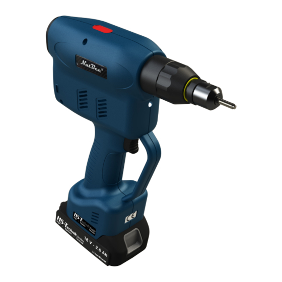
Tool structure 1. Start button 2. Traction head with mouthpiece 3. Multi-colour LED 4. 18 V Li-Ion battery 5. OLED Display 6. LED for work area lighting * Mouthpiece and threaded mandrel are not included in the standard scope of delivery and must be ordered separately. -
Page 22: Operation
Operation 4.2.1 Inserting and removing the battery • In order to insert the battery (1), align it so that it can be easily pushed onto the mount- ing provided along the plastic guide. After sliding it on completely, the fastening clip (2) must lock the battery firmly and properly into place in the tool housing. -
Page 23: Press Start Button
4.2.2 Press start button Pressing or actuating the start button starts or stops the tool. NOTE The battery riveting tool only starts when the battery has sufficient capacity. * - Start button 4.2.3 Front LED WARNING Risk of injury from the light emitting diode Looking directly into the light emitting diode can lead to eye injuries. -
Page 24: Led Indicator At The Back And Sound Signals
4.2.4 LED indicator at the back and sound signals Circumferential indicator lights up green after setting, no sound signal • Set stroke or set force was reached. • The battery capacity is sufficient, the tool is ready for the next setting. Circumferential indicator lights red after setting, no sound signal •... -
Page 25: Selection Of Threaded Mandrel And Mouthpiece
NOTE Assemble the traction heads only in accordance with the quick guides provided by HS-Technik GmbH. - 25 -... -
Page 26: Adjusting The Mouthpiece
4.2.7 Adjusting the mouthpiece The mouthpiece must be adjusted to the blind rivet nuts to be processed. Screw open blind rivet nuts by hand so that 1 - 2 threads stick out of the nut, see Figure 1. Lock the mouthpiece in this position using the lock nut. With automatic spinning on the threaded mandrel should now be flush with the blind rivet nut. - Page 27 1. Place the rivet on the mandrel. 2. Press start button and thread on blind rivet nut. While doing so hold the blind rivet nut as far forward as possible and do not reach into the opening. 3. Hold the start button down until the blind rivet nut has been completed threaded on; the tool stops automatically.
-
Page 28: Stroke Or Force Setting
4.2.9 Stroke or force setting Depending on the thread size and the material of the blind rivet nut and blind rivet screw, the stroke or level of force must be adjusted. In order to change the set stroke and set force of the tool proceed as follows: 1. -
Page 29: Setting Stroke Table For Nbls-21
4.2.10 Setting stroke table for NBLS-21 Serial no. Stroke Serial no. Stroke Serial no. Stroke Serial no. Stroke 0.10 mm 2.60 mm 5.25 mm 11.50 mm 0.20 mm 2.70 mm 5.50 mm 11.75 mm 0.30 mm 2.80 mm 5.75 mm 12.00 mm 0.40 mm 2.90 mm... -
Page 30: Setting Force Table For Nblf-25
4.2.11 Setting force table for NBLF-25 Serial no. Force Serial no. Force Serial no. Force Serial no. Force 2.00 kN 8.25 kN 14.50 kN 20.75 kN 2.25 kN 8.50 kN 14.75 kN 21.00 kN 2.50 kN 8.75 kN 15.00 kN 21.25 kN 2.75 kN 9.00 kN... -
Page 31: Spinning Off
4.2.12 Spinning off If an incorrect nut or screw is spun on or it is not currently needed it can easily be spun off. Clicking the yellow display button will make the notification „BACK“ appear in the display. The tool is ready to spin off the blind rivet nut or blind rivet screw next. -
Page 32: Overload
4.2.14 Overload In order to avoid damages as a result of excess temperatures during continuous operation it is important to observe sufficient break times during the installation process. If the tool should go into an automatic shut-down (TEMP FET) STOP as a result of excess temperatures the break times should be reviewed and adjusted. -
Page 33: Charge State Of The Battery
4.2.16 Charge state of the battery NOTE The tool will only start if the battery has sufficient charge capacity. When fully charged, the battery will display the charge state on the display on the left side as a green battery symbol. As the battery voltage decreases the colour of the symbol will change to yellow and then red. -
Page 34: Display Notifications
4.2.17 Display notifications Display notification Meaning Measure Undervoltage warning, Change / charge battery 17.44 V Battery empty (batt low 1) batt low 1 Battery empty (batt low 2) Change / charge battery 17.02 V Tool is not working anymore BATT LOW 2 Excess temperature „FET“... -
Page 35: Hst-Tool-Manager
If an update of your tool is necessary the HST- Tool-Manager will inform you. 1. Start the HST-Tool-Manager by double clicking the HST-Tool-Manager icon: 2. Log-in with the required User, a list of the passwords can be requested from HS-Technik (support@hs-technik.com). - 35 -... - Page 36 3. Insert the USB cable included into the Mini-B socket at the bottom of the tool and the opposite end into an open USB interface on your laptop / tablet / PC. 4. Click on the „read“ button on the top right. - 36 -...
- Page 37 5. The HST-Tool-Manager will now read the settings from your tool and will display its pro- gress using a green bar. At the end the tool overview will be displayed. - 37 -...
-
Page 38: Setup
4.3.1 Setup Clicking on setup takes you to the tool setup menu. Here, for example, the display, LED display and energy savings settings can be parametrised. 4.3.2 General → energy & lighting Here you can parametrise the energy saving options and the LED lighting. - 38 -... -
Page 39: General → Features
„energy saving“ The energy saving options can be activated or deactivated with the check-box. „display shut off after“ Time in seconds without action after which the OLED display of the tool will switch off and the screen saver will activate. Default value: 600 seconds (10 minutes) „tool shut off after“... -
Page 40: General → Tm Version
4.3.4 General → TM version The TM version will display the HST-Tool-Manager version required for this tool, at minimum, the version intended for the application, and the version last written on the tool. - 40 -... -
Page 41: Management
4.3.5 Management The location on the management tab and the inventory number of the tool can be saved under administration. Location max. 20 characters Inventory number max. 40 characters - 41 -... -
Page 42: Signals → Oled-Display
4.3.6 Signals → OLED-display „language“ Select the language on the OLED display, German or English Default: English Select the display of results on the OLED display. Smiley displays the „display of results“ result as Smiley with the process values as small, Force displays the force reached as large (for NBLF-25), Stroke displays the stroke value reached as large (for NBLS-21), Smiley large displays the result as Smiley without process values. -
Page 43: Signals → Led
4.3.7 Signals → LED The LED displays around the OLED display can be parametrised under the LED tab. The colour of the display can be changed by clicking on the coloured square. „duration“ The duration of the display in seconds, max. 25.5 seconds. „period“... -
Page 44: Signals → Sound Signals
4.3.8 Signals → sound signals „duration“ For the duration the time of the sound signal for OK and NOK results will be parametrised in seconds, max. value 3.0 seconds. „at start“ When the check-box is selected a signal will sound when the tool starts. - 44 -... -
Page 45: Signals → Vibration Alarm
4.3.9 Signals → vibration alarm „duration“ For the duration the time of the vibration for OK and NOK results will be parametrised in seconds. - 45 -... -
Page 46: Update
4.3.10 Update Select: Click on select and find the .upd file provided by HS-Technik GmbH. Click „start“. The progress of the update will be displayed using a status bar and confirmed at the end with „done“. The tool is now up-to-date with the current firmware and has the same settings as prior to the update. -
Page 47: Programming
4.3.11 Programming Clicking on „program“ takes you to the program settings menu. „selected stage“ The selected stage determines the programme of the table which is ac- tive. See programme table page 29 - 30. „enable change on This function activates and deactivates the setting of the programme us- ing the buttons under the OLED display. -
Page 48: Maintenance And Servicing
Maintenance and servicing Apart from the regular cleaning and the inspection and maintenance of the threaded mandrel the battery blind riveting device is largely maintenance-free. DANGER Risk of injury as a result of improper handling! Improperly executed work can lead to hazards. •... -
Page 49: Cleaning / Replacement Of The Threaded Mandrel
We recommend an annual machine capability study for high quality standards and a long life span. This can be combined with maintenance and inspection of the overall tool. The machine capability study can be completed by HS-Technik GmbH. - 49 -... -
Page 50: Service Interval Counter
4.5.4 Service interval counter The tool has an internal service interval counter which will inform the user of an inspection due. In this case you will receive the following notification in the display: 1 9 3 2 0 0 1 9 S e r v i c e B The service counters can be parametrised with the HST-Tool-Manager under the „Service“... -
Page 51: Storage
5 Storage Observe the following information when storing riveters, chargers and batteries: • Remove the battery when you are not using the riveting device. • If you will not be using the battery for a longer period of time it should be stored, fully charged, in a dry, dust-proof area. - Page 52 6 Technical data Description NBLS-21 NBLF-25 Operating voltage 18 VDC Device stroke 21 mm 25 mm Setting force max. 25 kN Setting speed max. 23 mm/s Noise emissions (L < 70 dB(A) Measurement uncertainty (K) 3 dB(A) Vibration (a < 2.5 m/s² Measurement uncertainty (K) 1.5 m/s²...
- Page 53 Specifications in mm Not shown to scale - 53 -...
- Page 54 7 Troubleshooting and Fault repair The NutBee by HS-Technik is a very stable and long-lasting tool. Please contact HS-Technik GmbH if unknown errors occur. Repairs: Telephone: +49 (0)7628 / 91 11-0 E-mail: repaircenter@hs-technik.com Programming: Telephone: +49 (0)7628 / 91 11-0 E-mail: support@hs-technik.com...
- Page 55 If the product or its accessories are modified without our consent, this declaration be- comes invalid. Tool description: Programmable cordless blind riveting tool Type designation: NBLx-xx Manufacturer: HS-Technik GmbH Im Martelacker 12 D-79588 Efringen-Kirchen Directives: 2006/42/EU 2014/30/EU Applied standards: DIN EN ISO 12100 2011-03...
- Page 56 HS-Technik GmbH Im Martelacker 12 D-79588 Efringen-Kirchen Telephone: +49 (0)7628 - 91 11-0 Fax: +49 (0)7628 - 91 11-90 E-mail: info@hs-technik.com Internet: www.hs-technik.com...
Need help?
Do you have a question about the NutBee NBLS-21 and is the answer not in the manual?
Questions and answers