
Related Manuals for HS-Technik RoboRiv


Summary of Contents for HS-Technik RoboRiv
- Page 1 OPERATING INSTRUCTIONS RoboRiv ® Note Issue date: April 2020 In case of doubt, the original German version of Tool Firmware: from 2.2.5.18 the operating instructions applies. HST-Tool-Manager: from 2.0.5.4...
-
Page 2: Table Of Contents
Information on the associated charger Structural modifications Cleaning the device and disposal 4 Start-up and use Tool structure Assembly of the RoboRiv Installation of the RoboRiv Operation 4.4.1 Inserting and removing the battery 4.4.2 LED indicator at the back and sound signals 4.4.3 OLED Display... - Page 3 4.6.2 General → energy & lighting 4.6.3 General → features 4.6.4 General → TM version 4.6.5 Management 4.6.6 Signals → OLED-display 4.6.7 Signals → LED 4.6.8 Signals → sound signals 4.6.9 Update 4.6.10 General → program Maintenance and servicing Cleaning 4.8.1 General information 4.8.2 Cleaning / replacement of the threaded mandrel 4.8.3 Machine capability test (MCT)
-
Page 4: Operating Principles
1 Operating principles Dear customers, Thank you for choosing a HS-Technik GmbH product. This quality product „Made in Germany“ fulfils the highest requirements with regard to performance, quality and accuracy. When used correctly the product will definitely perform very well for many years. - Page 5 This manual must be read and applied by every person who is assigned to conduct work using this tool. In addition to this operation manual the applicable regulations on accident prevention and environmental protection should be observed. NOTE After reading, keep the operating manual in a place accessibly to every operator.
-
Page 6: Signs And Symbols Used
Signs and symbols used The following signs and symbols will be used in this manual, or on the product: Symbol Explanation Read this operating manual Do not dispose of with household waste Do not dispose of the battery in a fire Do not throw the battery into water EU conformity marking ®... -
Page 7: Structure Of The Warnings
Structure of the warnings The warnings are structured as follows: DANGER Indicates an immediate dangerous situation that can lead to serious or even deadly injuries and / or that could seriously damage or even destroy the tool. WARNING Indicates a potentially dangerous situation that can lead to serious injuries and / or damage to the tool. -
Page 8: Intended Use
• following all indications of the operating instructions and • observance of inspection and maintenance works. Any other use or use beyond that is considered improper use. HS-Technik GmbH is not liable for any damage resulting from this. Improper use DANGER The use of this tool for other purposes, e.g. -
Page 9: Duties Of The Operator
Duties of the operator The operator undertakes to only allow people who are familiar with the basic regulations on occupational safety and accident prevention and who have been trained on how to use the tool at the workplace to work with this tool. The safety awareness of the personnel while working will be reviewed at regular intervals. -
Page 10: Training Of Personnel
1.10 Training of personnel Only trained and instructed personnel should work with this tool. The responsibilities of the personnel must be clearly defined. Trainees may only work with this power tool under the supervision of an experienced person. 1.11 Guarantee and liability Guarantee and liability claims for personal injury and property damage are excluded, if caused by one or more of the following: •... -
Page 11: Copyright
These operating instructions are intended solely for the operator and its personnel. They contain guidelines and information which may not be fully, or partially • reproduced • distributed or • otherwise shared. The copyright of these operating instructions is retained by HS-Technik GmbH. Manufacturer’s address: Im Martelacker 12 D-79588 Efringen-Kirchen Phone:... -
Page 12: General Safety Information For Power Tools
2 General safety information for power tools DANGER Read all the safety information, instructions, illustrations and technical data which is provided with this power tool. Failure to follow the instructions below may result in electric shock, fire and / or serious injury. WARNING This power tool was manufactured in according with current state-of-the-art technology and recognised technological safety guidelines. -
Page 13: Use And Handling Of Battery Tools
d) Keep unused power tools out of the reach of children. Do not let anyone use the power tool who is not familiar with it or has not read this manual. Power tools are dangerous when used by inexperienced people. e) Maintain power tools and the application tool with care. -
Page 14: Service
c) Keep the unused battery away from paper clips, coins, keys, nails, screws or other small metal parts which could cause a bypass of the contacts. Do not open the bat- tery and do not short circuit. A short circuit between the battery contacts can lead to burns or fire. -
Page 15: Important Information About This Tool
3 Important information about this tool Handling the associated lithium ion battery a) Observe the operation manual of the Li-Ion battery. b) If the battery will not be used over a longer period of time it may not remain on the charger or on the machine. -
Page 16: Information On The Associated Charger
No changes, additions or conversions to the power tool may be made without the approv- al of the manufacturer. All conversion measures require written consent and confirmation by HS-Technik GmbH. WARNING In the event of the replacement of wear and tear parts only original replacement parts may be used. -
Page 17: Cleaning The Device And Disposal
Cleaning the device and disposal Substances and materials used must be handled and disposed of properly, particularly when cleaning with solvents. Do not throw the used battery into the household waste, fire or water, instead have it professional disposed of by a specialist or the manufacturer. - 17 -... -
Page 18: Start-Up And Use
4 Start-up and use DANGER Risk of injury from damaged tools Damaged tools can lead to injuries or damages. • All damaged parts must be repaired before use. Risk of burns due to hot exhaust air Hot air can escape through exhaust openings. •... -
Page 19: Tool Structure
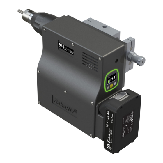
Tool structure 1. Power supply 2. 24V IO interface 3. Serial port 4. Compensation unit 5. 18 V Li-ion battery 6. Force sensor 7. Mouthpiece with threaded mandrel* 8. Display 9. Light barrier *Mouthpiece and threaded mandrel are not included in the standard scope of delivery and must be ordered separately. - 19 -... -
Page 20: Assembly Of The Roboriv
6 - Kraftsensor Assembly of the RoboRiv 7 - Gewindedorn 8 - Display The RoboRiv is connected to a higher-level system using the compensation unit. 4x M5 threads are provided for this (see drawing). 4 x M5 Schutzvermerk nac Tolerances in the travel and blind rivet can be balanced using the compensation unit. - Page 21 In the vertical case the contact pressure is achieved through the dead weight of the RoboRiv. It is important that no additional force is built up by the springs in the compensation unit.
-
Page 22: Installation Of The Roboriv
The following is needed for installation: • Tool • USB Cable included • PC • HST-Tool-Manager software (download at www.hs-technik.com/software) NOTE Always use the most current version of the HST-Tool-Manager. The software is backward compatible, i.e. it can also read and process older tool versions. -
Page 23: Operation
Operation 4.4.1 Inserting and removing the battery • In order to insert the battery (1), align it so that it can be easily pushed onto the moun- ting provided along the guide. After sliding it on completely, the fastening clip (2) must lock the battery firmly and properly into place in the tool housing. -
Page 24: Led Indicator At The Back And Sound Signals
4.4.2 LED indicator at the back and sound signals Led indication Description Release OK result NOK result Battery almost empty Action by operator necessary, see note on OLED display Approval if the signal for the set direction is at low through the 24V IO signals. -
Page 25: Oled Display
4.4.3 OLED Display After several seconds without actuation the display will dim. After longer downtime the tool will switch into standby mode. 1. Key for menu activation and selection as well as for the NOK confirmation 2. Key for decreasing value (-) 3. -
Page 26: Selection Of Threaded Mandrel And Mouthpiece
Do not use force, the traction head as well as the blind rivet nuts and blind rivet screws must be able to be tightened by hand. NOTE Assemble the traction heads only in accordance with the quick guides provided by HS-Technik GmbH. - 26 -... -
Page 27: Adjusting The Mouthpiece
4.4.5 Adjusting the mouthpiece The mouthpiece must be adjusted to the blind rivet nuts to be processed. Wind the blind rivet nuts by hand so that 1 - 2 threads stick out of the nut, see Figure 1. Lock the mouthpie- ce in this position using the lock nut. -
Page 28: Tool Start
If the battery is not empty only two undefined bytes are sent which do not need to be observed. iii. When starting the RoboRiv a signal is present at the NIO Pin and the IO pin each for a few milliseconds. - Page 29 1. At first, the RoboRiv must be brought into position for winding. To do this the RoboRiv must be driven onto the blind rivet nut until the threaded mandrel rests on it and the compensation unit is located in the centre of the guide. When this happens a signal is available on the position pin.
-
Page 30: Unwinding
4.4.8 Unwinding If an incorrect nut or screw is spun on or it is not currently needed it can easily be spun off. Clicking the yellow display button will make the notification „BACK“ appear in the display. The tool is ready to spin off the blind rivet nut or blind rivet screw next. -
Page 31: Use Of Tools And Maximum Load
4.4.10 Use of tools and maximum load In order to avoid damages as a result of excess temperatures during continuous operation it is important to ensure sufficient break times during the installation process. If the tool should go into an automatic shut-down (tempFET) as a result of excess temperatures, the pause times should be reviewed and adjusted. -
Page 32: Display
Display The display element in the HST-Tool-Manager can be changed so that, for example, precise values for the rivets, the stroke, only one OK or NOK or the count process can be displayed for the worker. The display elements can be displayed in German or English. In addition you can set which unit the values will be provided in (kN or lbf). -
Page 33: Display Notifications
4.5.1 Display notifications Display notification Meaning Battery status: 50 % - 100 % Battery status: 30 % - 50 % Battery status: 10 % - 30 % Battery status: 5 % - 10 % Battery status: less than 5 % The tool is ready for use. The blind rivet nut which was spun on can now be spun off. Hold the blind rivet nut (not by hand). - Page 34 Display notification Meaning The tool is approved for three blind rivets. The display is animated. Display settings HST-Tool-Manager: Signals - OLED display - Animation The tool is approved for three blind rivets. The display is animated. “P01” means that Programme 1 is activated. Display settings HST-Tool-Manager: Signals - OLED display –...
- Page 35 Display notification Meaning Both setting procedures were successful. Example of the NOK setting process: Process 1 NOK, 2 processes remaining. The error notification can be removed by clicking on the yellow button. The tension is displayed. After sliding the battery the notification „Trigger“...
- Page 36 Display notification Meaning The tool must be serviced. The notification can only be acknowl- edged by service personnel. Faulty sensor value, contact the manufacturer. Tare error The motor does not start correctly. Motor defective, incorrect programming or a mechanical clamping. Check the tension direction of the last step in your programme.
-
Page 37: Hst-Tool-Manager
A complete guide for the HST-Tool-Manager is available for you to download on our web- site. Download the current version of the HST-Tool-Manager in the downloads area on the HS-Technik website www.hs-technik.com. NOTE Always use the most current version of the HST-Tool-Manager from the website. - Page 38 3. Insert the USB cable included into the Mini-B socket at the bottom of the tool and the opposite end into an open USB interface on your laptop / tablet / PC. 4. Click on the „read“ button on the top right. - 38 -...
- Page 39 5. The HST-Tool-Manager will now read the settings from your tool and will display its progress using a green bar. At the end the tool overview will be displayed. - 39 -...
-
Page 40: Setup
4.6.1 Setup Clicking on „setup“ takes you to the tool settings menu. Here, for example, the display, LED display, and energy savings settings...can be parametrised. 4.6.2 General → energy & lighting Here you can parametrise the energy savings options and the LED lighting. - 40 -... -
Page 41: General → Features
„energy saving“ In the drop down menu you can select which action should follow when this level is OK, e.g. jump to the next level or end. „display shut off after“ Time in seconds without action after which the OLED display of the tool will switch off and the screen saver will activate. -
Page 42: General → Tm Version
4.6.4 General → TM version Which version of the HST-Tool-Manager is required for this tool, at minimum, which version is intended for the application, and which version was last written on the tool will be displayed in the TM tab. - 42 -... -
Page 43: Management
4.6.5 Management The data on the operating site and the inventory number of the tool can be saved under management. location max. 20 characters Inventory number max. 40 characters - 43 -... -
Page 44: Signals → Oled-Display
4.6.6 Signals → OLED-display „language“ Select the language on the OLED-display, German or English Default: English Select the display of results on the OLED display. Smiley displays the „display of results“ result as Smiley with the process values as small, Force displays the force reached as large (for NBLF-25), Stroke displays the stroke value reached as large (for NBLS-21), Smiley large displays the result as Smi- ley without process values. -
Page 45: Signals → Led
4.6.7 Signals → LED The LED displays around the OLED-display can be parametrised under the LED tab. The colour of the display can be changed by clicking on the coloured square. „duration“ The duration of the display in seconds, max. 25.5 seconds. „period“... -
Page 46: Signals → Sound Signals
4.6.8 Signals → sound signals „duration“ For the duration the time of the sound signal for OK and NOK results will be parametrised in seconds, max. value 3.0 seconds. „at start“ When the check-box is selected a signal will sound when the tool starts. - 46 -... -
Page 47: Update
4.6.9 Update select: Click on „select“ and select the .upd file provided by HS-Technik GmbH. Click „start“. The progress of the update will be displayed using a status bar and confirmed at the end with „done“. The tool is now up-to-date with the current firmware and has the same settings as prior to the update. -
Page 48: General → Program
A detailed guide on this can be found in the operations manual of our HST-Tool-Manager (download at www.hs-technik.com/software) NOTE We recommend using the support of the HS-Technik service personnel during initial start-up in order to determine the perfect parameters for your application. -
Page 49: Maintenance And Servicing
Maintenance and servicing Apart from the regular cleaning and the inspection and maintenance of the clamping jaws the battery blind riveting device is largely maintenance-free. WARNING Risk of injury as a result of improper handling! Repair, maintenance and care of riveting tools must be completed professionally. -
Page 50: Cleaning / Replacement Of The Threaded Mandrel
We recommend an annual machine capability test for high quality standards and a long life span. This can be combined with maintenance and inspection of the overall tool. The machine capability test can be completed by HS-Technik GmbH. - 50 -... -
Page 51: Service Interval Counter
4.8.4 Service interval counter The tool has an internal service interval counter which will inform the user of an inspection due. In this case you will receive the following notification in the display: 1 9 3 2 0 0 1 9 S e r v i c e B The service counters can be parametrised with the HST-Tool-Manager under the „Service“... -
Page 52: Interfaces
5 Interfaces Power Supply The Roboriv has a 2-pin socket for permanent charging of the Li-ion battery. NOTE The power supply must be well shielded because sensitive measurement technology is being used. Serial port The RoboRiv has an industrial USB A connection for transferring process data. Alternatively, the interface can also be designed with a 9-pin Sub-D connector via RS232. - Page 53 LIGHT_BARRIER +24 V START_PLC RESERVE _PLC POSITION_PLC IO_PLC NIO_PLC ACTIVE_PLC Technical data 24V inputs 2 pieces, each max. 10 mA 24V outputs 4 pieces, each max. 100 mA - 53 -...
-
Page 54: Storage
6 Storage Observe the following information when storage riveters and chargers: • Remove the battery when you are not using the riveting device. • If you will not be using the battery for a longer period of time it should be stored, fully charged, in a dry, dust-proof area. -
Page 55: Technical Data
7 Technical data Description RoboRiv Operating voltage 18 VDC Device stroke 21 mm Setting force max. 25 kN Setting speed max. 23 mm/s Power supply 24V, 1A Operating altitude < 2000 mNN Operating temperature 10 - 40 °C Storage temperature 0 - 50 °C Dimensions (L ×... -
Page 56: Drawings
Name Benennung: 12.12.2019 Bearb. H. Zetnik Freig. 17.12.2019 H. Zetnik Artikelnr.: Revision Blatt Zeichnungsnummer: Im Martelacker 12 Baugruppe RoboRiv 79588 Efringen-Kirchen Rev. Änderung Datum Name Ursprung: letzte Speicherung: 17.12.2019 112,1 Schutzvermerk nach Maße in mm Oberfläche ISO 16016 beachten Bearb. -
Page 57: Troubleshooting And Fault Repair
1. Battery empty 1. Replace and charge battery acoustic signal, red 2. Defective battery 2. Replace battery Light field appears If the error still persists or is not listed, please contact HS-Technik GmbH. Repairs: Telephone: +49 (0)7628 / 91 11-0 E-mail: repaircenter@hs-technik.com... -
Page 58: Declaration Of Conformity In Accordance With The Electromagnetic
If the product or its accessories are modified without our consent, this declaration be- comes invalid. Tool description: Programmable cordless blind riveting tool Type designation: RoboRiv® Manufacturer: HS-Technik GmbH Im Martelacker 12 D-79588 Efringen-Kirchen Directives: 2014/30/EU... -
Page 59: Ec Declaration Of Incorporation According To Machinery Directive 2006/42
If the product or its accessories are modified without our consent, this declaration be- comes invalid. Tool description: Programmable cordless blind riveting tool Type designation: RoboRiv® Manufacturer: HS-Technik GmbH Im Martelacker 12 D-79588 Efringen-Kirchen Directives: 2006/42/EC... -
Page 60: Annex To The Declaration Of Incorporation For Incomplete Machines
Annex to the declaration of incorporation for incomplete machines according to 2006/42/EC, Annex II, 1 B Description of the basic health and safety requirements according to 2006/42/EC, Annex I, which are used and met for the scope of the incomplete machine: ↓... - Page 61 ↓ Not relevant To be fulfilled by the system integrator ↓ ↓ For the scope of the incomplete machine fulfilled Protection against mechanical hazards × 1.3.1 Risk of loss of stability × 1.3.2 Risk of break-up during operation × 1.3.3 Risks due to falling or ejected objects ×...
- Page 62 ↓ Not relevant To be fulfilled by the system integrator ↓ ↓ For the scope of the incomplete machine fulfilled × 1.5.6 Fire × 1.5.7 Explosion × 1.5.8 Noise × 1.5.9 Vibrations × 1.5.10 Radiation × 1.5.11 External radiation × 1.5.12 Laser radiation ×...
- Page 63 ↓ Not relevant To be fulfilled by the system integrator ↓ ↓ For the scope of the incomplete machine fulfilled × 1.7.4.2 Contents of the instructions × 1.7.4.3 Sales literature Other from annex 1 Supplementary essential health and safety requirements for ×...
- Page 64 HS-Technik GmbH Im Martelacker 12 D-79588 Efringen-Kirchen Phone: +49 (0)7628 - 91 11-0 Fax: +49 (0)7628 - 91 11-90 E-Mail: info@hs-technik.com Internet: www.hs-technik.com...
Need help?
Do you have a question about the RoboRiv and is the answer not in the manual?
Questions and answers