Table of Contents
Advertisement
Quick Links
Advertisement
Table of Contents

Related Manuals for HS-Technik RivBee RBL-15x


Summary of Contents for HS-Technik RivBee RBL-15x
- Page 1 OPERATING INSTRUCTIONS RivBee ® - Original operating instructions - Battery blind rivet tool RBL-15x / RBL-20x NOTE Issue date: March 2021 In case of doubt, the original German version Tool Firmware: from 2.2.6.0 of the operating instructions applies. HST-Tool-Manager: from 2.0.6.0...
-
Page 2: Table Of Contents
Table of contents 1 Operating principles Scope of delivery General information Signs and symbols used Structure of the warnings Technical terms and abbreviations used Intended use Improper use Duties of the operator Duties of personnel 1.10 Training of personnel 1.11 Guarantee and liability 1.12 Copyright... - Page 3 4.2.16 Display notifications HST-Tool-Manager 4.3.1 Setup 4.3.2 General → Energy & Lighting 4.3.3 General → TM version 4.3.4 Management 4.3.5 Signals → OLED-display 4.3.6 Signals → Sound signals 4.3.7 Update 4.3.8 Programming 4.3.9 Program 4.3.10 Program → Option Maintenance and service Cleaning 4.5.1 General information 4.5.2 Clean clamping jaws...
-
Page 4: Operating Principles
1 Operating principles Dear customers, thank you for choosing a HS-Technik GmbH product. This quality product „Made in Germany“ fulfils the highest requirements with regard to performance, quality and accuracy. When used correctly the product will undoubtedly perform very well for many years. - Page 5 This operating instructions must be read and applied by every person who is assigned to conduct work using this tool. In addition to this operating instructions the applicable regulations on accident prevention and environmental protection should be observed. NOTE After reading, keep the operating instructions in a place accessible to every operator.
-
Page 6: Signs And Symbols Used
Signs and symbols used The following signs and symbols will be used in this operating instructions or on the product: Symbol Explanation Read this operating instructions Do not dispose with household waste Do not dispose the battery in a fire Do not throw the battery into water EU conformity marking ®... -
Page 7: Structure Of The Warnings
Structure of the warnings The warnings are structured as follows: DANGER Indicates an immediate dangerous situation that can lead to serious or even deadly injuries and/or that could seriously damage or even destroy the tool. WARNING Indicates a potentially dangerous situation that can lead to serious injuries and/or damage to the tool. -
Page 8: Intended Use
• following all indications of the operating instructions and • observance of inspection and maintenance works. Any other use or use beyond that is considered improper use. HS-Technik GmbH is not liable for any damage resulting from this. Improper use DANGER The use of this tool for other purposes, e.g. -
Page 9: Duties Of The Operator
Duties of the operator The operator undertakes to only allow people who are familiar with the basic regulations on occupational safety and accident prevention and who have been trained on how to use the tool at the workplace to work with this tool. The safety awareness of the personnel while working has to be reviewed at regular intervals. -
Page 10: Training Of Personnel
1.10 Training of personnel Only trained and instructed personnel should work with this tool. The responsibilities of the personnel must be clearly defined. Trainees may only work with this power tool under the supervision of an experienced person. 1.11 Guarantee and liability Guarantee and liability claims for personal injury and property damage are excluded, if caused by one or more of the following: •... -
Page 11: Copyright
These operating instructions are intended solely for the operator and its personnel. They contain guidelines and information which may not be fully, or partially • reproduced • distributed or • otherwise shared. The copyright of these operating instructions is retained by HS-Technik GmbH. Manufacturer’s address: Im Martelacker 12 D-79588 Efringen-Kirchen Telephone:... -
Page 12: General Safety Information For Power Tools
2 General safety information for power tools DANGER Read all the safety information, instructions, illustrations and technical data which is provided with this power tool. Failure to follow the instructions below may result in electric shock, fire and/or serious injury. WARNING This power tool was manufactured in according with current state-of-the-art technology and recognised technological safety guidelines. -
Page 13: Electrical Safety
Electrical safety a) Avoid body contact with grounded surfaces such as pipes, heaters, stoves and refrig- erators. There is an increased risk of electric shock if your body is grounded. b) Keep power tools away from rain or moisture. Penetration of water into a power tool increases the risk of electric shock. -
Page 14: Use And Handling Of Power Tools
e) Wear suitable clothing. Do not wear loose clothing or jewellery. Keep hair and cloth- ing away from moving parts. Loose clothing, jewellery or long hair can get caught in moving parts. f) Do not lull yourself into a false sense of security and do not disregard the safety rules for power tools, even if you are familiar with the power tool after repeated use. -
Page 15: Use And Handling Of Battery Tools
h) Keep handles and gripping surfaces dry, clean and free of oil and grease. Slippery handles and gripping surfaces do not allow safe operation and control of the power tool in unforeseen situations. i) Use the correct power tool. Do not use under-performing tools for heavy loads. Do not use tools for purposes and work for which they are not intended. -
Page 16: Service
g) Follow all instructions for charging and never charge the battery or the battery tool outside of the temperature range specified in the operating instructions. Incorrect charging or charging outside of the approved temperature range can damage the bat- tery and increase the risk of fire. Service a) Only have your power tool repaired by qualified professional staff and only with orig- inal replacement parts which can be available at HS Technik GmbH. -
Page 17: Important Information About This Tool
3 Important information about this tool Handling the associated lithium ion battery a) Observe the operating instructions of the Li-Ion battery. b) If the battery will not be used over a longer period of time it may not remain on the charger or on the machine. -
Page 18: Information On The Associated Charger
No changes, additions or conversions to the power tool may be made without the approval of the manufacturer. All conversion measures require written consent and confirmation by HS-Technik GmbH. WARNING In the event of the replacement of wear and tear parts only original replacement parts may be used. -
Page 19: Cleaning The Device And Disposal
Cleaning the device and disposal Substances and materials used must be handled and disposed of properly, particularly when cleaning with solvents. Do not throw the used battery into the household waste, fire or water, instead have it professional disposed of by a specialist or the manufacturer. - 19 -... -
Page 20: Start-Up And Use
4 Start-up and use DANGER Risk of injury from damaged tools Damaged tools can lead to injuries or damages. • All damaged parts must be repaired before use. Risk of injury from falling tools Falling tools can lead to injuries or damages. •... -
Page 21: Tool Structure
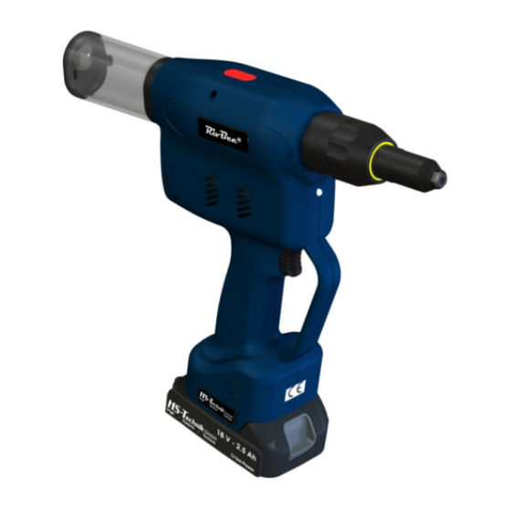
Tool structure 1. Start button 2. Traction head with mouthpiece 3. Riveting mandrel container 4. Multi-colour LED 5. 18 V Li-ion battery 6. OLED Display 7. LED for work area lighting - 21 -... -
Page 22: Operation
Operation 4.2.1 Inserting and removing the battery • In order to insert the battery (1), align it so that it can be easily pushed onto the mount- ing provided along the plastic guide. After sliding it on completely, the fastening clip (2) must lock the battery firmly and properly into place in the tool housing. -
Page 23: Press Start Button
4.2.2 Press start button Pressing or actuating the start button starts or stops the tool. NOTE The battery riveting tool only starts when the battery has sufficient capacity. * - Start button 4.2.3 Front LED WARNING Risk of injury from the light emitting diode Looking directly into the light emitting diode can lead to eye injuries. -
Page 24: Led Indicator At The Back And Sound Signals
4.2.4 LED indicator at the back and sound signals Circumferential indicator lights up green after setting, no sound signal • The parametrised setting was completed successfully. • The battery capacity is sufficient, the tool is ready for the next setting. Circumferential indicator lights red after setting, no sound signal •... -
Page 25: Empty Remaining Collection Container
4.2.6 Empty remaining collection container The riveting mandrel container for the torn off riveting mandrels must be emptied regularly. Turn the container by hand approx. 45° „counter clockwise“ or „clockwise“ in order to loosen it and remove it from the riveting machine. In order to place the riveting mandrel container back on after emptying align the noses and turn the riveting mandrel container approx. - Page 26 DANGER Risk of injury from projecting rivets Injuries can result if you do not use the original, undamaged riveting mandrel container • Always use only the original, undamaged riveting mandrel container • Ensure that the container is correctly installed (fully latched locking mechanism) In order to prevent use of the tool without a riveting mandrel container the riveting mandrel container is monitored using a sensor.
-
Page 27: Reducing Pipes
4.2.7 Reducing pipes We provide suitable reducing pipes for rivets with a mandrel diameter smaller than 3.2 mm for RBx-15 or smaller than 4.0 mm for RBx-20. Reducing pipes reduce the diameter of the guide tube through the tool and thereby prevent the remaining rivet mandrel from jamming in the guide tube. -
Page 28: Selection Of Nose Assembly
* There is no guarantee that all traction heads from the manufacturer’s named will fit. Contact us for further information. WARNING Risk of injury due to incorrect installation Incorrectly installed traction heads can lead to injuries • Assemble the traction heads only in accordance with the quick guides provided by HS-Technik GmbH - 28 -... -
Page 29: Set Fastener
4.2.10 Set fastener NOTE Always place the riveting tool at a right angle (90°) to the work surface to be riveted. An oblique placement leads to faulty riveting. Use only appropriate mouthpieces for the rivet. An incorrect mouthpiece can lead to damages in the clamping jaws as well as the mouthpiece. -
Page 30: Contact Pressure Sensor
4.2.11 Contact pressure sensor The pressure trigger ensures that the blind rivet can only be processed if the pressure trigger is activated. This prevents accidental triggering and ensures that the parts to be processed are lying next to each other. The pressure trigger can be deactivated in the HST-Tool-Manager as described below. -
Page 31: Quickriv-Technology
The pressure trigger can not be used in the following tool types due to the system: • RBx-15CH • RBx-20CH • RBx-15HU • RBx-20HU • RBx-20SFC-4 4.2.12 QuickRiv-Technology The tool has a monitor which automatically recognises when the rivet mandrel breaks and returns the tool back into the starting position. -
Page 32: Overload
4.2.13 Overload In order to avoid damages as a result of excess temperatures during continuous operation it is important to observe sufficient break times during the installation process. If the tool should go into an automatic shut-down (TEMP FET) as a result of excess temperatures the break times should STOP be reviewed and adjusted. -
Page 33: Charge State Of The Battery
4.2.15 Charge state of the battery NOTE The tool will only start if the battery has sufficient charge capacity. When fully charged, the battery will display the charge state on the display on the left side as a green battery symbol. As the battery voltage decreases the colour of the symbol will change to yellow and then red. -
Page 34: Display Notifications
4.2.16 Display notifications Display notification Meaning Required action Undervoltage warning, Change / charge battery 17.44 V Battery empty (batt low 1) batt low 1 Battery empty (batt low 2) Change / charge battery 17.02 V Tool is not working anymore BATT LOW 2 Excess temperature „FET“... -
Page 35: Hst-Tool-Manager
If an update of your tool is necessary the HST- Tool-Manager will inform you. 1. Start the HST-Tool-Manager by double clicking the HST-Tool-Manager icon: 2. Log-in with the required User, a list of the passwords can be requested from HS-Technik (support@hs-technik.com). - 35 -... - Page 36 3. Insert the USB cable included into the Mini-B socket at the bottom of the tool and the opposite end into an open USB interface on your laptop / tablet / PC. 4. Click on the „Read“ button on the top right - 36 -...
- Page 37 5. The HST-Tool-Manager will now read the settings from your tool and will display its progress using a green bar. At the end the tool overview will be displayed. - 37 -...
-
Page 38: Setup
4.3.1 Setup Clicking on setup takes you to the tool settings menu. Here, for example, the display, LED display, and energy savings settings...can be parametrised. 4.3.2 General → Energy & Lighting Here you can parametrise the energy saving options and the LED work lighting. - 38 -... -
Page 39: General → Tm Version
„energy saving“ The energy saving options can be activated or deactivated with the check-box. „display shut off after“ Time in seconds without action after which the OLED display of the tool will switch off and the screen saver will activate. Default value: 600 seconds (10 minutes) „tool shut off after“... -
Page 40: Management
4.3.4 Management The data on the operating site and the inventory number of the tool can be saved under management. Location max. 20 characters Inventory number max. 40 characters - 40 -... -
Page 41: Signals → Oled-Display
4.3.5 Signals → OLED-display „language“ Select the language on the OLED display, German or English Default: English „Rotate display 180°“ Selecting the check-box turns the display on the OLED display by 180°. - 41 -... -
Page 42: Signals → Sound Signals
4.3.6 Signals → Sound signals „At start“ When the check-box is selected a signal will sound when the tool starts. „Empty container If this check-box is selected a sound signal will sound in addition to the sound“ display notification when the riveting mandrel container needs to be emptied. -
Page 43: Update
Update Select Click on select and find the .upd file provided by HS-Technik GmbH. Please select automatic under „Recovery mode“. Then click „start“. The progress of the update will be displayed using a status bar and confirmed at the end with „done“. -
Page 44: Programming
4.3.8 Programming Clicking on „programming“ takes you to the program settings menu. Here you can set the speed, break recognition, contact pressure sensor, ..- 44 -... -
Page 45: Program
4.3.9 Program In program 1 up to 6 steps can be activated which can each be programmed individually. In order to set a step individual click the respective step. In order to create a new step click on the small blue plus sign on the top right in the step. step 1 When you have clicked on a step the overview appears in the image above. - Page 46 Sets the direction of the stroke. The default is „pulling direction“. The setting „start position“ is only required in special applications. In case of questions please contact our support at: support@hs-technik.com „start-up ramp“ This time defines which ramp the motor will drive to set rotation speed;...
- Page 47 „control method“ Setting the engine control. „Set speed“ is the default setting. In the „Regulate rpm“ control method the tool keeps the speed constant even under stress. “ „setting speed Sets the setting speed in % of the maximum speed. Recommended speed Target for closing the clamping jaws, step1: 50 %, for final setting, step 2: 80 - 100 %.
- Page 48 “ „I If I is activated I appears. This value defines the point at which Start Target start the stroke measurement for the setting step should be started. “ „I describes the maximum current which the tool may reach in this limit limit step.
- Page 49 0.25 „Current rejection“ This function suppresses the start-up current of the motor when using a current setting in the setting process. Recommended value: 0.25 seconds. - 49 -...
-
Page 50: Program → Option
4.3.10 Program → Option Under program options you can configure the options for the program. “ „I defines the minimum current for this step. If a current below this value is reached, no rivet will be set. The tool will display the message „blank stroke“... - Page 51 „QuickRiv-Technology“ The tool has a monitor which automatically recognises when the rivet mandrel breaks and returns the tool back into the starting position. De- pending on the traction head or fastener, the break detection must be deactivated. The break detection is active if the check-box is selected. „Pressure trigger“...
-
Page 52: Maintenance And Service
Maintenance and service Apart from the regular cleaning and the inspection and maintenance of the clamping jaws the battery blind riveting device is largely maintenance-free. WARNING Risk of injury as a result of improper handling! Repair, maintenance and care of riveting tools must be completed professionally. -
Page 53: Clean Clamping Jaws
4.5.2 Clean clamping jaws 1. Loosen cap nut 2. Pull sleeve away towards the front 3. Pull lock toward the back and hold, loosen clamping jaw housing 4. Remove clamping jaws 5. Clean or replace clamping jaws 6. Lubricate clamping jaws 7. -
Page 54: Service Interval Counter
4.5.3 Service interval counter The tool has an internal service interval counter which will inform the user of an inspection due. In this case you will receive the following notification in the display: 1 9 3 2 0 0 1 9 S e r v i c e B The service counters can be parametrised with the HST-Tool-Manager under the „Service“... -
Page 55: Storage
5 Storage Observe the following information when storing riveters and chargers: • Remove the battery when you are not using the riveting device. • If you will not be using the battery for a longer period of time it should be stored, fully charged, in a dry, dust-proof area. - Page 56 6 Technical data Description RBL-15X RBL-20X Operating voltage 18 VDC 18 VDC Device stroke 25 mm 25 mm Setting force max. 15 kN max. 20 kN Setting speed max. 47 mm/s max. 37 mm/s Noise emissions (L < 70 dB(A) <...
- Page 57 Specifications in mm Not shown to scale - 57 -...
- Page 58 - Check which stroke is required for the rivet for setting - Setting in the program config- - Check setting uration If the error still persists or is not listed, please contact HS-Technik GmbH. Repairs: Telephone: +49 (0)7628 / 91 11-0 E-mail: repaircenter@hs-technik.com...
- Page 59 If the product or its accessories are modified without our consent, this declaration becomes invalid. Tool description: Programmable cordless blind riveting tool Type designation: RBL-x… Manufacturer: HS-Technik GmbH Im Martelacker 12 D-79588 Efringen-Kirchen Directives: 2006/42/EU 2014/30/EU Applied standards: DIN EN ISO 12100 2011-03...
- Page 60 HS-Technik GmbH Im Martelacker 12 D-79588 Efringen-Kirchen Telephone: +49 (0)7628 - 91 11-0 Fax: +49 (0)7628 - 91 11-90 E-mail: info@hs-technik.com Internet: www.hs-technik.com...
Need help?
Do you have a question about the RivBee RBL-15x and is the answer not in the manual?
Questions and answers