
Related Manuals for Minnich A-1-48


Summary of Contents for Minnich A-1-48
-
Page 1: Chapter 1-Introduction
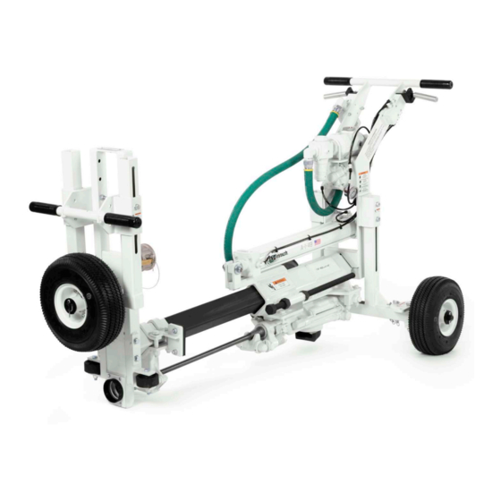
Minnich A-1-48 DOWEL DRILL OPERATOR/SERVICE MANUAL Minnich Manufacturing Contact 1444 ST RT 42 Phone: (419)-903-0010 Mansfield,OH 44903 Email: sales@minnich-mfg.com... -
Page 2: Table Of Contents
Pressure Regulator..........................20 Parts Manual............................22 Notes.................................26 Warranty..............................27 Parts Odering Online..........................28 It is Minnich’s policy to constantly strive to See engine manual for information pertaining improve our products. The information, spec- to the engine. ifications, and illustrations in this publication are based on the information in effect at the same time as approval for printing and pub- lishing. -
Page 3: General Warnings
GENERAL WARNINGS CALIFORNIA PROPOSITION 65 Engine exhaust and some of its constituents, and some dust created by power sanding, sawing, grinding, drilling and other construction activities contains chemicals known to the Sate of California to cause cancer, birth defects and other reproductive harm. -
Page 4: General Safety
GENERAL SAFETY Do not operate or service the equipment before SAFETY SYMBOLS reading the entire manual. Safety precautions Potential hazards associated with the operation should be followed at all times when operating this of this equipment will be referenced with hazards equipment. - Page 5 ∆ Never use accessories or attachments that are glasses, respirator protection, hearing pro- not recommended by Minnich for the equip- tection, steel-toes boots and other protec- ment. Damage to the equipment and/or injury tive devises required by the job or city and to user may result.
- Page 6 GENERAL SAFETY ENVIRONMENTAL SAFETY/DECOMMISSIONING ∆ DO NOT expose vibrator to rain. ∆ DO NOT use vibrator motor in damp or wet ∆ DO NOT pour waste or oil directly into the locations without proper electrical circuits. ground, down a drain or into any water ∆...
- Page 7 ∆ Make sure air line is cleaned out and is of the PINCH PIVOT POINTS proper size and pressure rating for the drill unit. ∆ Make sure the lubricator is filled with proper lubricant. See Minnich recommended lubricant below. Dowel Drill Manual...
- Page 8 Placement and consolidation To find the latest revision of this publication, visit our website at: www.minnich-mfg.com The force exerted by an internal concrete vibra- tor is controlled by the weight and the speed at which the eccentric rotates. The centrifugal...
-
Page 9: General Specifications
GENERAL SPECIFICATION A-1-48 Specifications The A-1 can be configured four different ways. There is no need to purchase extra conversion kits. 1. Two wheel on grade for more accurate drilling 2. One wheel on grade for drilling 6” (15.2cm) to corner 3. - Page 10 GENERAL SPECIFICATION Pneumatic Connection: • Approved air disconnect is required to be installed in accordance to Local & National Codes. Environmental: • +5°C to +40°C (+41°F to +104°F) • 50% Rh at +40°C (+104°F), (90% Rh at +20°C (+68°F)) • Altitude – 1000m (3280ft) above mean sea level •...
-
Page 11: Safety Decal Location
SAFETY DECAL LOCATION All safety labels on Minnich Manufacturing units have been carefully placed so they can be easily seen at all times. There are several different types of labels on the units. Always keep these warnings free of dirt, concrete, or anything else that restricts visibility. - Page 12 INSTALL LOCK 12287-10 12287-12 PIN PRIOR TO TRANSPORTING MACHINE 12287-7 INSTALL LOCK PIN PRIOR TO TRANSPORTING MACHINE 12287-7 Minnich Mfg. Recommended Rock Drill Oil INSTALL LOCK 12287-62 12287-62 PIN PRIOR TO TRANSPORTING MACHINE 12287-7 Bio-Rock Drill Oil 15W50 12287-62 12287-62...
-
Page 13: Drill Steel Information
All war- 5. On average you can get 180 holes, 9” ranty claims must be submitted to Minnich (228.6mm) deep per bit. for evaluation and sent to the supplier for 6. - Page 14 DRILL STEEL & BITS OPTIONS 1 Piece Steel & Bit (Whirly Bit) Part Number Hole Diameter Shank Size UC Length 005367-12.00 5/8” (15.9mm) 7/8” x 4 1/4” (22.2mm x 107.9mm) 12” (30.5cm) 005367-24.00 5/8” (15.9mm) 7/8” x 4 1/4” (22.2mm x 107.9mm) 24”...
-
Page 15: Usage Calculation
USAGE CALCULATION Usage Calculation The calculations below are nominal and could vary depending on the hardness of the concrete, aggregates used and the possibility of bits hitting steel reinforcement. Whirly Bit, Taper Bit and “H” Thread Bit (B)Bit=180 holes x 9” (22.86cm) B=1620”... -
Page 16: Set Up Operation
SET-UP OPERATION Step 1 Be sure lubricator is full. See recommended oils below. Step 2 Make sure slab wheels are square against face of slab. Step 3 Using feed control valve, feed bit against slab. Step 4 Using drill control valve, turn drill on and drill until the drill slider is against the stop clamp, which should be set for the required depth of hole. -
Page 17: Trouble Shooting
TROUBLE SHOOTING AIR DRILL PROBLEM: DRILL DOES NOT RUN Cause Remedy DRILL NOT GETTING AIR 1. On Multi Drill units, switch airline with drill that is working properly. If drill now runs check the air control valve. If the valve works, check the drill. - Page 18 TROUBLE SHOOTING AIR DRILL PROBLEM: DRILL RUNS SLOW OR DOES NOT DRILL EFFECTIVELY Cause Remedy NOT ENOUGH AIR REACHING On Multi Drill units. Turn off one or two drills. If DRILL. IT SHOULD HAVE 100SCFM the remaining drills pick up speed, check the air (47.2DM^3/ .) PER DRILL AND 110 compressor.
-
Page 19: Cylinder Service Kits
CYLINDER SERVICE KITS Obsolete Style Cylinder: Bushing held in place by snap ring. Service parts no longer available. Current Style Cylinder: Bushing threaded in Rod Diameter place. Service parts listed below. Oversize Rod Cylinders (Feed) Standard Rod Cylinders Rod Diameter Service Kit Part # Rod Diameter Service Kit Part #... -
Page 20: Pressure Regulator
PRESSURE REGULATOR MINNICH P/N 002880-00000 OPERATION A regulator is used in a compressed air system to maintain nearly constant outlet pressure despite changes in the inlet air pressure and changes in downstream flow requirements. Outlet pressure is controlled by the adjusting screw (1). clockwise rotation increases and counter- clockwise rotation decreases outlet pressure setting. - Page 21 PRESSURE REGULATOR MINNICH P/N 009626-00010 INSTILLATION nstall regulators so the airflow is in the direction of the arrow as indicated on the head of unit. Regula- tors should be installed downstream from filters and upstream from lubricators, but as close as possible to the pneumatic tools or appliances being serviced.
-
Page 22: Chapter 2-Parts Manual
PARTS MANUAL Dowel Drill Manual... - Page 23 PARTS MANUAL Dowel Drill Manual...
- Page 24 LUBRICATOR PARTS MANUAL LUBRICATOR MINNICH P/N 001864-00000 CAPACITY: 0.5 PINT (237mL) PIPE SIZE: 3/4” (1.9cm) N.P.T. Item Number Minnich Part Number Description 001864-00001 Feeder Assembly Kit 001864-00002 Manual Relieving Safety Cap 001864-00003 Sight Window 001864-00004 Check Valve (Constant Feed) 006412-00916...
- Page 25 HAMMER PARTS MANUAL 50# (23kg) Rock Drill0A9350-00000 When ordering replacement parts you need to furnish the model and serial number of the drill tool. FIG. Part # Description FIG. Part # Description 009350-00001 BACKHEAD ASSEMBLY 009350-00056 RIFLE NUT 009350-00013 AIR CONNECTION WASHER 009350-00057 PISTON 009350-00016...
-
Page 26: Notes
NOTES Dowel Drill Manual... -
Page 27: Warranty
The product must have been purchased resulting from the installation or removal of this directly from Minnich or from an authorized product from any installation, any unauthorized Minnich reseller. tampering with this product, any repairs at-... -
Page 28: Parts Odering Online
Scan for Helpful Videos! WE ACCEPT THE FOLLOWING CARDS! NON-DEALER AND INTERNATIONAL COSTUMERS: Contact Minnich Manufacturing through the following num- ber to locate a dealer near you. (419-903-0010) All orders are treated as Standard Orders and will ship the same day if received prior to...
Need help?
Do you have a question about the A-1-48 and is the answer not in the manual?
Questions and answers