
Related Manuals for GFA SG 50


Summary of Contents for GFA SG 50
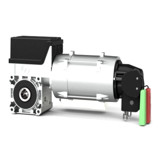
- Page 1 Installation Instructions ELEKTROMAT SE 9.15-25,40 Model: 10003277 10012 -en- Status: 26.03.2021...
- Page 2 GfA ELEKTROMATEN GmbH & Co. KG Wiesenstraße 81 D-40549 Düsseldorf www.gfa-elektromaten.de info@gfa-elektromaten.de...
-
Page 3: Table Of Contents
Table of contents General safety information ....................4 Safe operation ......................... 4 Technical Data ........................ 6 Mechanical installation ....................7 Electrical installation ..................... 11 Limit switch adjustment ....................12 Motor connection ...................... -
Page 4: General Safety Information
The safe operation of the product can only be ensured if it is used as specified. Follow the installation instructions. Observe all specifications, especially warnings, when installing the product in the overall system. GfA is not liable for damage resulting from non-observance of the installation instructions. The resulting overall system must be reassessed for its safety in accordance with applicable standards and directives (e.g. - Page 5 Warning - Failure to follow these installation instructions may result in severe injury or death. Please read these instructions before using the product. Keep these instructions handy. Include these instructions when passing on the product to third parties. Warning - Danger from improper use of the product! ...
-
Page 6: Technical Data
2 Technical Data Type SG 50 Output torque Output speed Output shaft / hollow shaft 25,40 Maximum output speed open / close 26 / 26 for frequency inverter operation Maximum holding torque Maximum door weight 4000 Supply voltage 3N~ 400... -
Page 7: Mechanical Installation
3 Mechanical installation Prerequisites The permissible loads on walls, fastenings, mountings and transmission elements must not be exceeded, even for maximum holding torques or locking torques (▶ refer to technical data). Connection elements: ▶ Self-locking connection ▶ Utilize the hole diameter ▶... - Page 8 Mounting Eight threads are provided for mounting. ▶ Use at least 2 of these (①). Keys are used to connect to the door shaft. ▶ Use a key that is at least as long as the hollow shaft (②). BAGAD0 1 0 0 1 _Z0 0 2 8 x (M8x16)
- Page 9 Installation The descriptions below apply to general door specifications. The specifications of the door manufacturer must also be observed during installation. Warning - Potential injury or danger to life! During installation, be sure to use a lifting device that has a sufficient load- carrying capacity.
- Page 10 ▶ Attach the drive unit. BAGAE0 1 0 0 3 _Z0 0 3 ▶ Tighten all connection elements (M8) to 25 BAGAE0 1 0 0 6 _Z0 0 2 Nm. Install all other connection elements according to the specifications of the door manufacturer.
-
Page 11: Electrical Installation
4 Electrical installation Warning - Danger to life from electric current! Switch the mains OFF and check that the cables are de-energised Observe the applicable regulations and standards Make a proper electrical connection Use suitable tools Performing electrical installation Remove the cover. -
Page 12: Limit Switch Adjustment
5 Limit switch adjustment The adjustment of the final limit positions OPEN and CLOSE is described in the instructions for the door control panel. -
Page 13: Motor Connection
6 Motor connection Motor X13 Motor plug 7 Alternative motor connection Motor X13 Motor plug... -
Page 14: Limit Switch Connection
8 Limit switch connection Thermal contact S10 Emergency manual operation X12 DES connection Safety circuit Channel B (RS485) Ground Channel A (RS485) Safety circuit Supply voltage... -
Page 15: Emergency Manual Operation (Rapid Hand Chain Operator)
9 Emergency manual operation (rapid hand chain operator) Emergency manual operation is designed for opening or closing the door without power supply. Its activation interrupts the control voltage. Electrical operation is no longer possible. Warning – Injuries due to incorrect operation! ... - Page 16 Switch on by pulling the red handle. Open or close by pulling the chain. Switch off by pulling the green handle.
-
Page 17: Completing Commissioning / Inspection
10 Completing commissioning / inspection Check the following components and then install all covers. Gearbox Check the drive unit for loss of oil (a few drops can be neglected). Protect the output-shaft permanently against corrosion. Mounting Check that all connection elements (consoles, torque mounts, screws, locking rings, etc.) are secure and in proper condition. -
Page 18: Declaration Of Incorporation / Declaration Of Conformity
EMC Directive 2014/30/EU within the meaning of RoHS Directive 2011/65/EU The following requirements from Appendix I of GfA ELEKTROMATEN GmbH & Co. KG the Machinery Directive 2006/42/EC are met: declare under our sole responsibility that the 1.1.2, 1.1.3, 1.1.5, 1.2.2, 1.2.3, 1.2.6, 1.3.2,...
Need help?
Do you have a question about the SG 50 and is the answer not in the manual?
Questions and answers