Advertisement
Quick Links
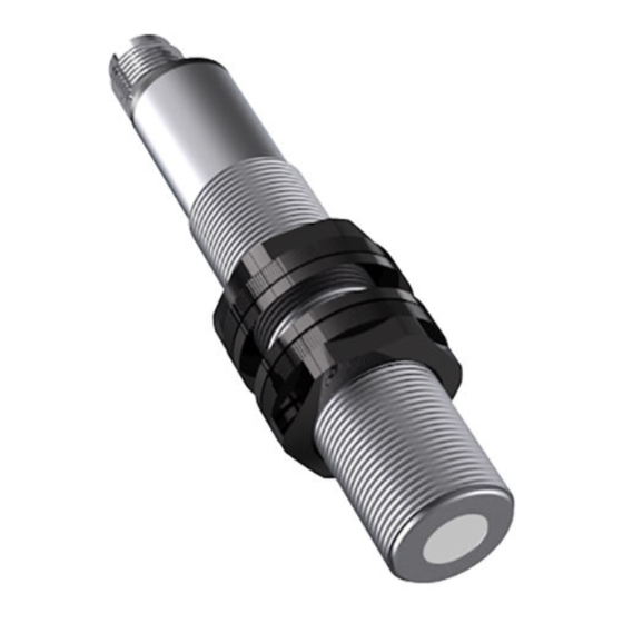
INSTALLATION GUIDE
Ultrasonic Sensors Series UFP and UPA
For further information please see the data sheet at www.waycon.biz/products/ultrasonic-sensors
FIRST STEPS
WayCon Positionsmesstechnik GmbH would like to thank you for the trust you have placed in us and
our products. This manual will make you familiar with the installation and operation of our ultrasonic
sensors. Please read this manual carefully before initial operation!
Unpacking and checking:
Carefully lift the device out of the box by grabbing the housing. After unpacking the device, check
it for any visible damage as a result of rough handling during the shipment. Check the delivery for
completeness. If necessary, consult the transportation company, or contact WayCon directly.
MOUNTING THE SENSOR
• Ultrasonic sensors may be installed in any position, as long as depositions like dust, spray mist, or
condensing humidity are avoided on the sound active membrane.
• It is important to avoid structure-borne sound bridges between the sensor and its holder.
• In case several ultrasonic sensors are used in one application, it is important to leave sufficient
distance between them. Otherwise the sensors may interact which leads to false measurement
values.
• By using a sound deflection angle the sound beam can be redirected, at the expense of the sensor's
maximum measurement range. A plain and hard surface should be used for the defection of the
sound beam. Redirecting the sound beam with multiple sound deflection angles should be avoided.
ELECTRICAL CONNECTION
UFP-200
Pin
1
2
3
4
Analog / Switching output
Connection cable
Function
+V
Teach-In
GND
K4P
BN
WH
BU
BK
connector output
M12 (male)
3
4
2
1
Advertisement

Related Manuals for Waycon UFP Series


Summary of Contents for Waycon UFP Series
- Page 1 For further information please see the data sheet at www.waycon.biz/products/ultrasonic-sensors FIRST STEPS WayCon Positionsmesstechnik GmbH would like to thank you for the trust you have placed in us and our products. This manual will make you familiar with the installation and operation of our ultrasonic sensors.
-
Page 2: Electrical Connection
ELECTRICAL CONNECTION UFP-400...3500, UPA-6000 connector output M12 (male) Analog output Switching output Connection cable K5P Switching point P2 Analog Switching point P1 Teach-In Teach-In DETECTION BEAMS –15 The exact geometry of the sound cone depends on the air-pressure, temperature, humidity and the –15 size of the target. -
Page 3: Technical Drawing
TECHNICAL DRAWING UFP-200 ±0.5 47.5 AF17 UFP-400/500/800/1600/2000 69.5 11.2 Model UFP-400 UFP-500/800/1600/2000 AF24 UFP-3500 ±0.5 ±0.5 11.2 AF36 UPA-6000 □80 M12x1... - Page 4 LEDS UFP-400/500/800/ UFP-200 UPA-6000 ±0.5 1600/2000/3500 47.5 EC P1 P2 AF17 EC (Echo LED) green: is on, when an echo is received (alignment LED). P1, P2 LED yellow: LEDs P1 and P2 indicate the status of the switching outputs (UFP-200: just P1). TEACHING THE ANALOG OUTPUT Every sensor is delivered with the factory set-up (max.
- Page 5 TEACHING THE ANALOG OUTPUT Teach-In of P2 (SP2 position) Connect the Teach-In line with GND until the P2 and Echo LEDs start blinking with a 2 Hz frequency (UFP-200 just yellow, 1 Hz). First P1 and Echo LEDs will be blinking, but it is important to wait to reach P2.
- Page 6 TEACHING THE SWITCHING OUTPUT Teach-In of P2 (SP2 position): Connect the Teach-In line with GND until the P2 and Echo LEDs start blinking with a 2 Hz frequency. First P1 and Echo LEDs will be blinking but it is important to wait to reach P2. The sensor is now in Teach-In mode for P2: P1 LED blinks with 1 Hz frequency now.
-
Page 7: Environmental Influences
INFLUENCES ON THE MEASUREMENT Environmental influences: Ultrasonic sensors are made for the use in atmospheric air. Environmental Influences like rain, snow, dust or smoke have no influence on the accuracy of the measurement. However, measurements under pressure (higher that the atmospheric pressure) are not possible with ultrasound sensors. Strong wind or air turbulences may lead to instability in measurement values. -
Page 8: Declaration Of Eu-Conformity
DECLARATION OF EU-CONFORMITY WayCon Positionsmesstechnik GmbH Mehlbeerenstraße 4 82024 Taufkirchen / Germany This is to certify that the products Classification Ultrasonic Sensors Series UFP, UPA fulfil the current request of the following EC-directives: EMC-directive 2014/30/EU applied harmonized standards: EN 60947-5-2: 2007 + A1:2012, EN 60947-5-7:9/2003 The declaration of conformity loses its validity if the product is misused or modified without proper authorisation.