Table of Contents
Advertisement
Quick Links
INSTALLATION GUIDE
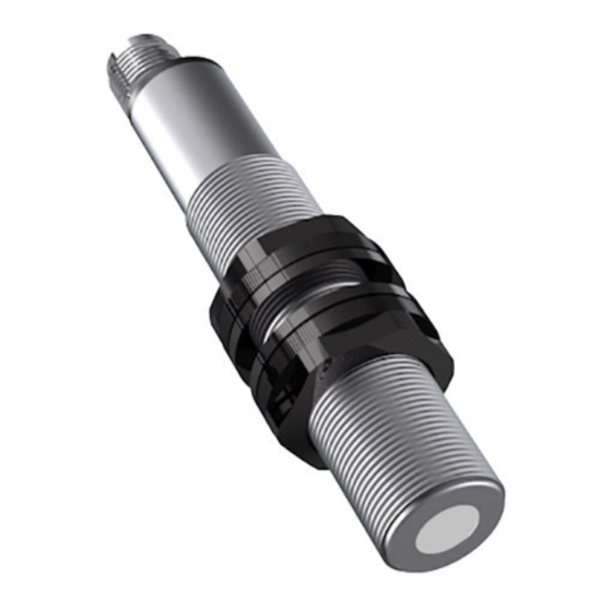
Ultrasonic Sensors Series UFP
For further information please see the data sheet at www.waycon.biz/products/ultrasonic-sensors/
FIRST STEPS
WayCon Positionsmesstechnik GmbH would like to thank you for the trust you have placed in us and our
products. This manual will make you familiar with the installation and operation of our ultrasonic sensors.
Please read this manual carefully before initial operation!
Unpacking and checking:
Carefully lift the device out of the box by grabbing the housing. After unpacking the device, check it for
any visible damage as a result of rough handling during the shipment. Check the delivery for
completeness. If necessary consult the transportation company, or contact WayCon directly.
MOUNTING THE SENSOR
Ultrasonic sensors may be installed in any position, as long as depositions like dust, spray mist, or
condensing humidity are avoided on the sound active membrane.
It is important to avoid structure-borne sound bridges between the sensor and it's holder.
In case several ultrasonic sensors are used in one application, it is important to leave sufficient distance
between them. Otherwise the sensors may interact which leads to false measurement values.
By using a sound deflection angle the sound beam can be redirected, at the expense of the sensor's
maximum measurement range. A plain and hard surface should be used for the defection of the sound
beam. Redirecting the sound beam with multiple sound deflection angles should be avoided.
ELECTRICAL CONNECTION
UFP-200
Pin 1
+24 V
Pin 2
Teach-In
Pin 3
0 V
Pin 4
Switch, Analog Output
UFP-400 to 3500, Analog Output
Pin 1
+24 V
Pin 3
0 V
Pin 4
Analog Output
Pin 5
Teach-In
UFP-400 to 3500, Switching Output
Pin 1
+24 V
Pin 2
Switching Point P2
Pin 3
0 V
Pin 4
Switching Point P1
Pin 5
Teach-In
Advertisement
Table of Contents

Related Manuals for Waycon UFP Series


Summary of Contents for Waycon UFP Series
- Page 1 For further information please see the data sheet at www.waycon.biz/products/ultrasonic-sensors/ FIRST STEPS WayCon Positionsmesstechnik GmbH would like to thank you for the trust you have placed in us and our products. This manual will make you familiar with the installation and operation of our ultrasonic sensors.
- Page 2 INSTALLATION GUIDE Ultrasonic Sensors Series UFP For further information please see the data sheet at www.waycon.biz/products/ultrasonic-sensors/ TECHNICAL DRAWING UFP-200 range: 250 mm output: 1 x switching point or 0...10 V UFP-400/ 500/ 800/ 1600/ 2000: range up to 2000 mm output: 2 x switching points or 0...10 V or 4...20 mA...
- Page 3 SOUND CONE GEOMETRY The exact geometry of the sound cone depends on the air-pressure, temperature, humidity and the size of the target. UFP-200 UFP-400 UFP-500 UFP-800 UFP-1600 UFP-2000 UFP-3500 Guaranteed detection of a target 100 x 100 mm Possible detection of a large target...
- Page 4 TEACH-IN GUIDE Ultrasonic Sensors Series UFP For further information please see the data sheet at www.waycon.biz/products/ultrasonic-sensors/ INTRODUCTION Sensor with analog output: Every sensor is delivered with the factory set-up (max. measuring range). The teach-in feature is designed to choose a smaller range within the nominal measuring range for optimizing the resolution and linearity.
- Page 5 TEACHING THE ANALOG OUTPUT Teach-In of P1 (SP1 position) Connect Teach In line with GND until P1 and Echo LEDs start blinking with a 2 Hz frequency (UFP-200 just yellow). and then release the contact. The sensor is now in the Teach In mode for P1: P1 LED will now blink with 1 Hz frequency (UFP-200 with ½...
- Page 6 TEACH-IN GUIDE Ultrasonic Sensors Series UFP For further information please see the data sheet at www.waycon.biz/products/ultrasonic-sensors/ TEACHING THE SWITCHING OUTPUT Normal Switching Function Teach In of P1 (SP1 position) Connect Teach In line with GND until P1 and Echo LEDs start blinking with a 2 Hz frequency and then release the contact.
- Page 7 NOTES Warning These devices are not designed for critical safety or emergency shut-down purposes. Therefore they should never be used in an application, where a malfunction of the device could cause personal injury. Environmental Influences Ultrasonic sensors are made for the use in atmospheric air. Environmental Influences like rain, snow, dust or smoke have no influence on the accuracy of the measurement.
- Page 8 DECLARATION OF EC-CONFORMITY WayCon Positionsmesstechnik GmbH Mehlbeerenstrasse 4 82024 Taufkirchen / Germany This is to certify that the products Classification Ultrasonic Sensors Series fulfill the current request of the following EC-directives: EMV-directive...
Need help?
Do you have a question about the UFP Series and is the answer not in the manual?
Questions and answers