
Related Manuals for Waycon EZ 105 Series


Summary of Contents for Waycon EZ 105 Series
- Page 1 Installation Guide MHM-97883 , Rev 1.01 February 2019 ™ Machinery Health Sensor EZ 10xx, Eddy Current Sensors...
- Page 2 Information in this document is subject to change without notice and does not represent a commitment on the part of WayCon. The information in this manual is not all-inclusive and cannot cover all unique situations.
-
Page 3: Table Of Contents
Contents Contents General ............................1 Chapter 1 Using this manual ............................1 Symbols..............................2 Liability and guarantee ..........................2 Incoming goods inspection ........................2 Technical support ............................3 Storage and transport ..........................3 Disposal of the device ..........................3 China RoHS Compliance ........................... 4 Installation awareness.......................... - Page 4 Contents [iv]...
-
Page 5: Chapter 1 General
General General Topics covered in this chapter: • Using this manual • Symbols • Liability and guarantee • Incoming goods inspection • Technical support • Storage and transport Disposal of the device • • China RoHS Compliance Installation awareness • Using this manual This manual contains information concerning the proper and correct use of the device. -
Page 6: Symbols
DC voltage. Liability and guarantee WayCon is not liable for damages that occur due to improper use. Proper use also includes the knowledge of, and compliance with, this document. Customer changes to the device that have not been approved expressly by WayCon will result in the loss of guarantee. -
Page 7: Technical Support
Product Service Center. Before shipping this product, contact WayCon Product Support to obtain a Return Materials Authorization (RMA) number and receive additional instructions. Product Support WayCon provides a variety of ways to reach your Product Support team to get the answers you need when you need them: Phone... -
Page 8: China Rohs Compliance
General • Recyclable metal • Plastic elements Sort the remaining components for disposal, based on their condition. National laws or provisions on waste disposal and protection of the environment apply. Note Environmental hazards! Electrical waste and electronic components are subject to treatment as special waste and may only be disposed by approved specialized companies. - Page 9 General • Use a sensor that meets the requirements of the defined measuring range. • Ensure an EMC-compatible installation including the use of proper cables. • Ensure proper function of the measurement before activating the measurement for regular operation.
- Page 10 General...
-
Page 11: Chapter 2 Safety Instructions
Safety instructions Safety instructions Topics covered in this chapter: • Using the device • Owner's responsibility To ensure safe operation, carefully observe all instructions in this manual. The correct and safe use of this device requires that operating and service personnel both understand and comply with general safety guidelines and observe the special safety comments listed in this manual. - Page 12 Safety instructions Related information Environmental conditions...
-
Page 13: Application And Design
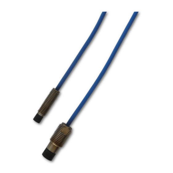
Application and Design Application and Design Topics covered in this chapter: • The Sensors • The Measuring Chain The Sensors The 5 mm and 8 mm sensors EZ 105x and EZ 108x are available in different variants. With Chapter 7 Figure 3-1 or without the optional EZ 190x extension cable. - Page 14 Application and Design Figure 3-1: Design EZ 105x and EZ 108x Plug with cap nut of the extension cable EZ 190x extension cable (optional) Connection (plug of the sensor cable with cap nut and socket of the extension cable) Sensor cable EZ 10xx Eddy Current Sensor Unthreaded part of the sensor case Sensor head...
-
Page 15: The Measuring Chain
Application and Design The Measuring Chain An EZ 105x or EZ 108x sensor, together with the EZ 1000 converter, form the eddy current measuring chain. Use this measuring chain for contactless distance, vibration, or speed measurements. Different types of sensors and the software-configurable EZ 1000 converter allow an optimal adaption to the requirements of the machine to be monitored. - Page 16 Application and Design [12]...
-
Page 17: Installation And Mounting
(see Section 4.2.1). To measure shaft vibration, WayCon recommends using a sensor holder between bearing and turbine housing, as close as possible to the rotor. [13]... -
Page 18: Mount The Sensor
Installation and Mounting Figure 4-1: Example scheme where to place the sensors Measuring collar Trigger wheel Measuring chain for measuring shaft displacement with EZ 1000 and EZ 105x or EZ 108x. Measuring chain for measuring shaft vibration with EZ 1000 and EZ 105x or EZ 108x. Measuring chain for measuring speed/key with EZ 1000 and EZ 105x or EZ 108x. -
Page 19: Requirements And Hints For The Sensor Mounting
Installation and Mounting Do not bend or twist the sensor cable. If the sensor cable has an adapter plug, open To avoid touching the shaft during installation, the maximum distance between measuring target and sensor head must be adjusted first. Screw in the sensor until the converter output voltage starts changing (approximately at -20V DC). - Page 20 Installation and Mounting which are not related to a real position or vibration signal. The signal caused by these irregularities is called runout. For the measuring track, WayCon recommends a surface finish of 0.41 µm to 0.76 µm. Free space Ensure there is 45°...
- Page 21 Installation and Mounting Figure 4-3: Maximum axial tilting S: distance between measuring target and sensor head a: maximal axial tilting angle < 2° Maximum tangential offset Ensure the maximum tangential offset matches the values in Table 4-1. Figure 4-4 shows the definition of the tangential offset.
-
Page 22: Wiring Hints
Installation and Mounting Minimum measuring area Ensure that the minimum measuring area matches the values in Table 4-2. Figure 4-5 shows the definition of the minimum measuring area. Table 4-2: Minimum measuring area Sensor type X minimum Sensor head diameter EZ 105x 5 mm 5.2 mm... -
Page 23: Sensor With Extension Cable
Installation and Mounting • Ensure that no parts of the cable, including the adapter plug, touch any rotating parts of the machine. • Note that machines can expand or shrink due to temperature influences. Always install the sensor cable with a cable length reserve to compensate the thermal behavior of the machine. - Page 24 Installation and Mounting Figure 4-6: Overview shrink sleeve Blue shrink sleeve – only necessary for installations at hazardous locations. Black shrink sleeve Plug of the sensor cable Socket of the extension cable Apply shrink sleeve to a connector At the open connection, push the black shrink sleeve over one connector so that the sleeve completely covers the sensor cable.
-
Page 25: Chapter 5 Technical Data
Technical data Technical data Topics covered in this chapter: • Measuring targets • Measuring ranges and sensitivity • Environmental conditions Only specifications with tolerances are guaranteed. Data without tolerance or without error limits are informative data and not guaranteed. Technology is under constant development, and specifications are subject to change without notice. -
Page 26: Environmental Conditions
Technical data Sensor EZ 105x EZ 108x Nominal measuring range, 25 ... 250 µm 50 ... 500 µm dynamic, peak − peak (recommended) Sensitivity for 42 Cr Mo 4 16 V/mm 8 V/mm Value for nominal distance at 0.75 mm 1.5 mm the center point of converter output signal... -
Page 27: Drawings
Drawings Drawings Figure 6-1: EZ 1050-xx-xx-xxx Unthreaded length (see Chapter 7 for available lengths) Case length (see Chapter 7 for available lengths) Overall cable length (see Chapter 7 for available lengths, tolerance 0 ... +10%) All dimension in mm. [23]... - Page 28 Drawings Figure 6-2: EZ1051-xx-xx-xxx Unthreaded length (see Chapter 7 for available lengths) Case length (see Chapter 7 for available lengths) Overall cable length (see Chapter 7 for available lengths, tolerance 0 ... +10%) All dimension in mm. [24]...
- Page 29 Drawings Figure 6-5: EZ 1080-xx-xx-xxx WS8 spanner flat not available with 20 mm (0.8 in) and unthreaded length case Case length (see Chapter 7 for available lengths) Unthreaded length (see Chapter 7 for available lengths) Overall cable length (see Chapter 7 for available lengths, tolerance 0 ...
- Page 30 Drawings Figure 6-6: EZ 1081-xx-xx-xxx * WS8 spanner flat not available with 20 mm (0.8 in) and unthreaded length case Case length (see Chapter 7 for available lengths) Unthreaded length (see Chapter 7 for available lengths) Overall cable length (see Chapter 7 for available lengths, tolerance 0 ...
-
Page 31: Chapter 7 Order Information
Drawings Order information The EZ 105x and EZ 108x sensors can be ordered in different variations according to Table 7-1 Table 7-2. Use the EZ 190x extension cable to adjust the cable length to your needs (see Table 7-3). Note Ensure that the overall cable length, sensor cable plus extension cable, does not exceed 10 meters. - Page 32 T +49 89 679713 - 0 specifications of our products at any time without notice. F +49 89 679713 - 250 All rights reserved. The WayCon logo is a trademark. All other www.waycon.biz marks are property of their respective owners.
Need help?
Do you have a question about the EZ 105 Series and is the answer not in the manual?
Questions and answers