Table of Contents

Related Manuals for Lincoln Electric POSIMATIC PS30


Summary of Contents for Lincoln Electric POSIMATIC PS30
- Page 1 POSITIONERS POSIMATIC PS30 SAFETY INSTRUCTIONS FOR USE AND MAINTENANCE POSIMATIC PS30 W000385394 POSIMATIC PS30 PLASMA 95032131NG 8695 6650 EDITION : EN Instructions for use REF : REVISION : C DATE : 10-2019 Original instructions...
- Page 2 Thank for the trust you have expressed by purchasing this equipment, which will give you full satisfaction if you follow its instructions for use and maintenance. Its design, component specifications and workmanship comply with applicable European directives. Please refer to the enclosed CE declaration to identify the directives applicable to it.
-
Page 3: Table Of Contents
E - OPERATOR MANUAL ......................... 18 1 - CONTROL BUTTONS ON CABINET ................. 18 F - MAINTENANCE ..........................20 1 - SERVICING ......................... 20 2 - TROUBLESHOOTING ......................25 3 - SPARE PARTS ........................29 PERSONAL NOTES .......................... 34 POSIMATIC PS30... - Page 4 For operating instructions, adjustments, troubleshooting and spare parts see safety instructions for use and maintenance. REVISIONS REVISION B 11/17 DESIGNATION PAGE Update E-18 ; D-17 ; F-31 REVISION C 10/19 DESIGNATION PAGE To change logos POSIMATIC PS30...
-
Page 5: A - Identification
8695 6650 / C A - IDENTIFICATION Please enter the number of your machine in the following box. Quote this information in all correspondence. Manufacturing factory code Year manufactured Manufacturing year code Product type Product serial no. POSIMATIC PS30... -
Page 6: B - Safety Instructions
Do not exceed the tilting and rotating torques which determine the maximum admissible load (see diagrams on the equipment). Do not let loads fall hard on the equipment. Fully tighten the workpiece(s) on the positioner table. POSIMATIC PS30... -
Page 7: Important Recommendations
When starting-up or when changing a connection, there is one chance in two that the connection of phases will be inverted, in which case the tilt limit switches become totally ineffective and there are great risks of damage (refer to chapter page D17). POSIMATIC PS30... -
Page 8: C - Description
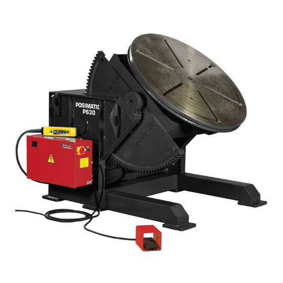
C - DESCRIPTION 1 - DESCRIPTION POSIMATIC PS30 is a device which enables parts with varied shapes to be positioned in order to optimize operations such as welding, oxycutting, resurfacing, metallization, etc. by presenting the working line in the best position. - Page 9 C - DESCRIPTION 8695 6650 / C b) Dimensions and space requirements POSIMATIC PS30 POSIMATIC PS30...
- Page 10 Admissible load in daN (Y1) in relation to the distance in mm (L1) of the part centre of gravity in relation to the surface of the plate. 1300000 Authorized area Prohibited area (vertical plate) Load in daN Distance / plate in mm POSIMATIC PS30...
- Page 11 Admissible load in daN (Y2) in relation to the distance in mm (L2) between the centre of gravity and the rotation axis. 450000 Y Authorized area Prohibited area (vertical plate) Load in daN Distance / plate in mm POSIMATIC PS30...
-
Page 12: Detailed Description
Cogged quadrant Tilting frame Plate Electrical cabinet The POSIMATIC PS30 mainly comprises a frame (M1) in which the tilting mechanical (M2) components are mounted. It supports the rotating plate (M9). The frame (M1) supports also : The tilting gearbox (M3). - Page 13 Grooves are provided to accommodate bolts in such a maner that bolts cannot be accidently remove from the slots. The central hole Ø40 is extended by a tube that runs through the tilting frame (M2). It allows the gas supply for welding applications for example. Dimensions of grooves POSIMATIC PS30...
- Page 14 A wheel and worm reduction gear (E5-M6) transmits the rotation movement to the cogged ring (M8) through the drive gear (M7). Speed control is made via a potentiometer fixed on the pushbutton box. A graduated dial shows speed setting. POSIMATIC PS30 C-10...
- Page 15 The axis (M20) is mounted on bearings (M18) in the frame (M1). The box (M2) is hinged on two horizontal trunnions (M12) mounted in bushes housed in the frame (M1) and accommodates the fixed part of the positioning ring (M8). POSIMATIC PS30 C-11...
- Page 16 Rotating plate Welding ground connection POSIMATIC PS30 is fitted with four ground connectors (M10). They are made up of an assembly with two brushes pushed by springs that rub against the plate (M9). The capacity of this welding ground connection (1000A for a 100% duty factor) is such that it enables nearly all welding processes to be used.
- Page 17 Two limit switches (E7) switch off motor power supply when the mobile sub-assembly reaches the extreme position (0° and 135°). Toothing protective A toothing protective (M11) keeps the operator safe by eliminating the risks from the rotating mechanism (M8 and M7) . POSIMATIC PS30 C-13...
-
Page 18: D - Assembly - Installation
Sling the POSIMATIC in its wooden packaging as indicated in the drawing. Unpack the POSIMATIC from its delivery packaging. Sling the POSIMATIC, always using the slinging eyes which are provided for moving. Operator protection : Helmet - Gloves - Safety shoes POSIMATIC PS30 D-14... -
Page 19: Putting In Place
We market cabinets that meet the criteria set out. ARRANGEMENT OF CABLES AND FLEXIBLE HOSES The customer must provide a means to support and protect cables and flexible hoses from mechanical, chemical or thermal damage, right from their point of origin. POSIMATIC PS30 D-15... - Page 20 - 148 and 44 for right - hand rotation - 148 and 43 for left - hand rotation - 148 and 53 for horizontal tilting - 148 et 54 for vertical tilting POSIMATIC PS30 D-16...
-
Page 21: Installation
the plate rises: invert two phases at the connection of the mains supply When these tests are conclusive, the positioner is ready for starting-up. Repeat these checks each time the positioner is moved. POSIMATIC PS30 D-17... -
Page 22: E - Operator Manual
Switch with three fixed positions for rotation direction. The central position is the idle position. Switch with three fixed positions for tiling direction. The central position is the idle position. Pedal to allow the rotation movement of the plate. POSIMATIC PS30 E-18... - Page 23 E - OPERATOR MANUAL 8695 6650 / C POSIMATIC PS30 E-19...
-
Page 24: F - Maintenance
Further, the main parts of the equipment, particularly the coggings, the screws and nuts, power cables of motors and remote control, motor ventilation etc., must be inspected periodically. After a long time of unusing the positioner, all the periodical controls should be done before restarting. POSIMATIC PS30 F-20... - Page 25 Esso beacon 2 (bearing) when plate is unmounted. Bearings of the Grease the bearing with the Esso beacon 2 tilting drive gears help of greasers Drain the gearboxes and fill Oil HAFA SYNTEC Gearboxes them with new oil POSIMATIC PS30 F-21...
- Page 26 EVERY 2 WEEKS Parts Operations Lubrication 1) Check the condition of the teeth of the cogged sector of the tilting mechanism GEARS Grease HPG 400 2) Grease the cogging of the positioning ring Check the tension BELTS POSIMATIC PS30 F-22...
- Page 27 Check the wear state. Check the wear state. Belts Check the adjustment of the air gap and wear state of the Brake of the tilting pad (see procedure). Replace pad before exceeding the motor minimum limit thickness (1.5mm). POSIMATIC PS30 F-23...
- Page 28 With a unbraking lever, a too large air gap can lead to a null braking torque. WARNING : The distance « X » has to be higher than in the table. The thickness of the brake pad has to be higher than 1.5mm. POSIMATIC PS30 F-24...
-
Page 29: Troubleshooting
- a variable drive fault F0102 or suddenly. F0103 Check that the terminals U, V and W of the variable drive are not shorted. Check that the motor cable is not shorted and that the motor is correctly coupled. POSIMATIC PS30 F-25... - Page 30 Check that you have followed the table with the admissible load and unbalance values for your positioner Check that the load has not increased suddenly. Check that the motor cable is not shorted and that the motor is correctly coupled. POSIMATIC PS30 F-26...
- Page 31 Input signal at X12.4 too low. Increase the value A4000 The voltage of the DC bus has reached the minimum value POSITIONER FUSES RATINGS STANDARD POSITIONERS FU1 (5x20) FU2 (10x38) FU3 (5x20) POSIMATIC PS30 1 A FsT 6 A aM 6 A FsF POSIMATIC PS30 F-27...
- Page 32 F - MAINTENANCE 8695 6650 / C POSIMATIC PS30 F-28...
-
Page 33: Spare Parts
W000XXXXXX Carte interface machine W000XXXXXX Débitmètre 9357 XXXX Tôlerie face avant sérigraphiée For parts order, give the quantity required and put the number of your machine in the box below. TYPE : Number : POSIMATIC PS30 F-29... - Page 34 F - MAINTENANCE 8695 6650 / C MECHANICAL PART POSIMATIC PS30 F-30...
- Page 35 Belt W000386976 W000386976 Pulley W000386977 W000386977 Pulley W000386987 W000386987 Sensor For parts order, give the quantity required and put the number of your machine in the box below. TYPE : Number : POSIMATIC PS30 F-31...
- Page 36 F - MAINTENANCE 8695 6650 / C ELECTRICAL PART POSIMATIC PS30 F-32...
- Page 37 2 contact relay 9503 2002 9503 2002 Control box with cable W000273453 W000273453 Pedal For parts order, give the quantity required and put the number of your machine in the box below. TYPE : Number : POSIMATIC PS30 F-33...
-
Page 38: Personal Notes
F - MAINTENANCE 8695 6650 / C PERSONAL NOTES Lincoln Electric France S.A.S. Avenue Franklin Roosevelt 76120 Le Grand Quevilly 76121 Le Grand Quevilly cedex www.lincolnelectriceurope.com POSIMATIC PS30 F-34...