Advertisement
Table of Contents
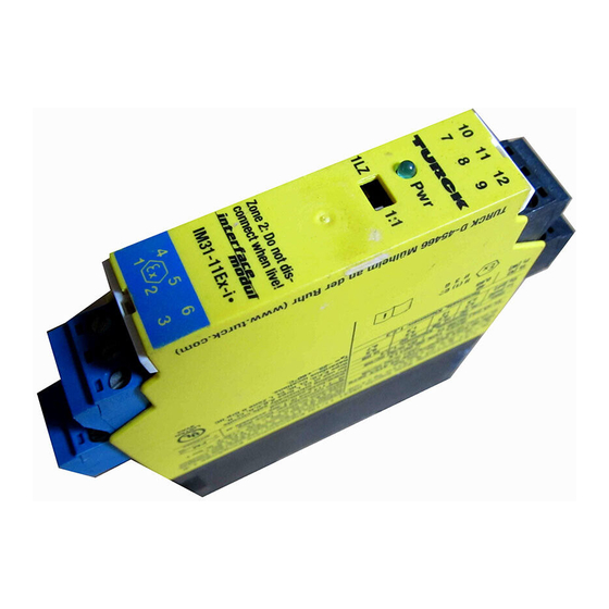
- 1 Short Description
- 2 Pin Configuration (Fig. 2)
- 3 LED Indications (Fig. 1 + 2)
- 4 Function Adjustment (Fig. 1)
- 5 Mounting and Installation (Fig. 3)
- 6 Special Conditions for Application in Zone 2
- 7 Important Information on Use of Devices with Intrinsically Safe Circuits
- 8 EC-Type Examination Certificate
- Download this manual
Analogsignaltrenner
IM31-11Ex-i/...-U
IM31-12Ex-i/...-U
IM31-22Ex-i/...-U
Gerätekurzbeschreibung
•
Galvanisch getrennte Übertragung von
normierten Analogsignalen
•
Eingangskreise eigensicher Ex ia
•
Anwendungsbereich nach ATEX:
II (1) G, II (1) D, II 3 G
•
Zugelassen für Einbau in Zone 2
•
Alternativer Anschluss von normierten
aktiven Spannungs- oder Stromsignalen
•
Umwandlung von Dead-zero nach Live-
zero, d. h. 0...20 mA bzw. 0...10 V nach
4...20 mA bzw. 2...10 V
•
Abziehbare Klemmenblöcke mit Codierung
•
Gerätetypen:
– IM31-11Ex-i/...-U: einkanalig
– IM31-12Ex-i/...-U: einkanalig mit Signal-
verdoppelung
– IM31-22Ex-i/...-U: zweikanalig
Anschlussbelegung (Fig. 2)
1, 3; 4, 6
Spannungseingang (passiv)
2, 3; 5, 6
Stromeingang (passiv)
7, 10; 8, 9 Stromausgang (aktiv)
7, 10; 8, 9 Spannungsausgang (aktiv)
11, 12
Betriebsspannungsanschluss gemäß
seitlicher Gehäusebedruckung
Leitungsanschluss durch anhebende Käfige mit
unverlierbaren Schrauben, Anschlussquerschnitt:
≤ 1 × 2,5 mm
, 2 × 1,5 mm
oder 2 × 1 mm
2
2
Ader-Endhüsen, max. Anzugsdrehmoment: 0,5 Nm
LED-Anzeigen (Fig. 1 + 2)
Pwr
grün
Betriebsbereitschaft
Fig. 1
10
11
12
10
11
12
7
8
9
7
8
9
Pwr
Pwr
1LZ
1:1
1LZ
1:1
2LZ
1:1
Zone 2: Do not dis-
Zone 2: Do not dis-
connect when live!
connect when live!
IM31-11Ex-...
IM31-12Ex-...
4
5
6
4
5
6
1
2
3
1
2
3
Analog data transmitter
IM31-11Ex-i/...-U
IM31-12Ex-i/...-U
IM31-22Ex-i/...-U
Short description
•
Galvanically isolated transmission of
standard analogue signals
•
Intrinsically safe input circuit Ex ia
•
Area of application acc. to ATEX:
II (1) G, II (1) D, II 3 G
•
Approved for installation in zone 2
•
Alternative connection of standard active
voltage or current signals
•
Conversion from Dead-Zero to Live-Zero, i.e.
0...20 mA or 0...10 V to 4...20 mA or 2...10 V
•
Removeable terminal blocks with coding
•
Device types:
– IM31-11Ex-i/...-U: single-channel
– IM31-12Ex-i/...-U: single-channel with
– IM31-22Ex-i/...-U: dual channel
Pin Configuration (Fig. 2)
1, 3; 4, 6
voltage input (passive)
2, 3; 5, 6
current input (passive)
7, 10; 8, 9 current output (active)
7, 10; 8, 9 voltage output (active)
11, 12
supply voltage connection according
to side imprint on housing
Connection via lifting cages with captive screws,
connection profile: ≤ 1 × 2.5 mm
mit
or 2 × 1 mm
with wire sleeves, max. tightening
2
2
torque: 0.5 Nm
LED indications (Fig. 1 + 2)
Pwr
green
Fig. 2
0/4...20 mA
1
alternat.
0/2...10 V
10
11
12
7
8
9
Pwr
0/4...20 mA
1LZ
1:1
2LZ
1:1
alternat.
1
0/2...10 V
Zone 2: Do not dis-
connect when live!
IM31- 22 Ex-...
0/4...20 mA
4
5
6
1
alternat.
1
2
3
0/2...10 V
0/4...20 mA
2
alternat.
0/2...10 V
Séparateur de signaux
analogiques
IM31-11Ex-i/...-U
IM31-12Ex-i/...-U
IM31-22Ex-i/...-U
Description brève
•
•
•
•
•
•
•
•
signal duplication
Raccordement (Fig. 2)
1, 3; 4, 6
2, 3; 5, 6
7, 10; 8, 9 sortie courant (active)
7, 10; 8, 9 sortie tension (active)
11, 12
Raccordement du câble par des bornes à cage
, 2 × 1.5 mm
levantes avec des vis imperdables, section raccor-
2
2
dable: ≤ 1 × 2,5 mm
avec cosses, , couple de serrage max. 0,5 Nm
Visualisation par LED (Fig. 1 + 2)
Power on
Pwr
+ 2
7 +
50 W
10 –
– 3
11
Pwr
50 kW
+ 1
GN
12
IM31-11Ex-i
7 +
10 –
+ 2
50 W
8 +
– 3
9 –
50 kW
+ 1
11
Pwr
GN
12
IM31-12Ex-i
+ 2
7 +
50 W
– 3
10 –
50 kW
+ 1
8 +
9 –
+ 5
50 W
– 6
11
Pwr
50 kW
12
GN
+ 4
IM31-22Ex-i
Transmission de signaux de analogiques
normalisés, séparés galvaniquement
Circuits d'entrée à sécurité intrinseque Ex ia
Champ d'application suivant ATEX:
II (1) G, II (1) D, II 3 G
Certifié pour montage en zone 2
Raccordement alternatif de signaux de
tension ou de courant actifs normalisés
Conversion de dead-zéro en live-zéro, c.-à-d.
de 0...20 mA ou 0...10 V en 4...20 mA
ou 2...10 V
Blocs de bornes débrochables avec codage
Types d'appareils:
– IM31-11Ex-i/...-U: monocanal
– IM31-12Ex-i/...-U: monocanal avec dou-
blement des signaux
– IM31-22Ex-i/...-U: deux canaux
entrée tension (passive)
entrée courant (passive)
raccordement de la tension de service
suivant l'impression latérale sur l'appareil
, 2 × 1,5 mm
ou 2 × 1 mm
2
2
verte
tension de service
1
1
7 +
0/4…20 mA
0/2…10 V
10 –
R L £ 500 W
R L ³ 500 W
11
Pwr
Power
Power
GN
12
IM31-11Ex-U
7 +
1
1
10 –
0/2…10 V
0/4…20 mA
R L ³ 500 W
R L £ 500 W
8 +
2
2
9 –
11
Pwr
Power
Power
GN
12
IM31-12Ex-U
7 +
1
1
10 –
0/4…20 mA
0/2…10 V
R L £ 500 W
R L ³ 500 W
8 +
2
2
9 –
11
Pwr
Power
Power
GN
12
IM31-22Ex-U
2
Advertisement
Table of Contents

Related Manuals for turck IM31-11Ex-i U Series

Summary of Contents for turck IM31-11Ex-i U Series
- Page 1 Analogsignaltrenner Analog data transmitter Séparateur de signaux IM31-11Ex-i/...-U IM31-11Ex-i/...-U analogiques IM31-12Ex-i/...-U IM31-12Ex-i/...-U IM31-11Ex-i/...-U IM31-22Ex-i/...-U IM31-22Ex-i/...-U IM31-12Ex-i/...-U IM31-22Ex-i/...-U Gerätekurzbeschreibung Short description Description brève • • • Galvanisch getrennte Übertragung von Galvanically isolated transmission of Transmission de signaux de analogiques normierten Analogsignalen standard analogue signals normalisés, séparés galvaniquement •...
- Page 2 IM31-...Ex-... Funktionseinstellung (Fig. 1) Function adjustment (Fig. 1) Réglage des fonctions (Fig. 1) Mit einem (bzw. zwei) Frontschalter(n) lässt sich The transfer characteristics can be adjusted (see Les deux commutateurs (ou un) en face fron- die Übertragungscharakteristik einstellen also table 1) with one (or two) front switches. tale permettent de régler la caractéristique de (siehe auch dazu Tab.
- Page 3 All valid national and interna- Les données essentielles de l‘attestation d‘examen CE internationalen Bescheinigungen der TURCK-Geräte finden Sie tional approvals covering Turck devices are obtainable via the figurent au verso. L‘ensemble des certificats nationaux et Internet (www.turck.com). The special conditions of IECEx CoC im Internet (www.turck.com).
- Page 4 Irrtümer und Änderungen vorbehalten / Subject to change without notice / Sous réserve de modifications • © Hans Turck GmbH & Co. KG 2013 Hans Turck GmbH & Co. KG • Witzlebenstraße 7 • 45472 Mülheim/Ruhr • Germany • Tel. +49 208/4952-0 • Fax +49 208/4952-264 • more@turck.com • www.turck.com...
Need help?
Do you have a question about the IM31-11Ex-i U Series and is the answer not in the manual?
Questions and answers