Table of Contents
Advertisement
Quick Links
dvbLOGiC DVB-T2 / DVB-T Tuner
Compatible with BMW Professional
Product features
• Full plug and play vehicle-specific dual DVB-T / DVB-T2 Tuner + USB-AV-Player
• DVB-T2 HEVC/H265/264 and DVB-T MPEG2/MPEG4 compatible
• Recording function for broadcasted TV
• AFS - auto frequency switching
• USB-AV-Player for USB-media (audio, video, photo) up to 2TB (FAT32 and NTFS)
• Support of all common Audio & Video formats (e.g MPEG-I/II/IV, H264, H265,
VOB, AVI, DivX, Xvid, MKV, TS, MOV, RMVB, mp3, WAV, AAC)
• USB-AV-Player with last position memory for Audio and Video playback
• with two antenna adapters and USB extension with installation socket
• integrated into and controllable by vehicle infotainment
• AV-input with IR-control channel
• control of after-market devices, e.g. DVD-player, DAB+ tuner
• after-market rear-view camera input
• automatic or manual switching to after-market rear-view camera input (only from
dvbLOGiC mode)
• rear-seat-entertainment AV-output for AV-sources connected to the dvbLOGiC
• optional remote control for full DVB-tuner and USB AV-Player functions/rear-seat-
entertainment
• power-on remote-out trigger-signal (+12V max 1A) to switch on connected devices
• video-in-motion
Version 25.09.2017
DT3-CXC-TV1
navigation systems
CCC and CIC with iDrive
Vehicles with factory TV-tuner port
(Factory TV-tuner must be uninstalled)
DT3-CXC-TV1
Advertisement
Table of Contents

Subscribe to Our Youtube Channel
Related Manuals for Caraudio-Systems dvbLOGiC DT3-CXC-TV1

Summary of Contents for Caraudio-Systems dvbLOGiC DT3-CXC-TV1
- Page 1 dvbLOGiC DVB-T2 / DVB-T Tuner DT3-CXC-TV1 Compatible with BMW Professional navigation systems CCC and CIC with iDrive Vehicles with factory TV-tuner port (Factory TV-tuner must be uninstalled) Product features • Full plug and play vehicle-specific dual DVB-T / DVB-T2 Tuner + USB-AV-Player • DVB-T2 HEVC/H265/264 and DVB-T MPEG2/MPEG4 compatible • Recording function for broadcasted TV • AFS - auto frequency switching • USB-AV-Player for USB-media (audio, video, photo) up to 2TB (FAT32 and NTFS) • Support of all common Audio & Video formats (e.g MPEG-I/II/IV, H264, H265, VOB, AVI, DivX, Xvid, MKV, TS, MOV, RMVB, mp3, WAV, AAC) • USB-AV-Player with last position memory for Audio and Video playback • with two antenna adapters and USB extension with installation socket • integrated into and controllable by vehicle infotainment • AV-input with IR-control channel • control of after-market devices, e.g. DVD-player, DAB+ tuner • after-market rear-view camera input • automatic or manual switching to after-market rear-view camera input (only from dvbLOGiC mode) • rear-seat-entertainment AV-output for AV-sources connected to the dvbLOGiC • optional remote control for full DVB-tuner and USB AV-Player functions/rear-seat- entertainment • power-on remote-out trigger-signal (+12V max 1A) to switch on connected devices • video-in-motion Version 25.09.2017 DT3-CXC-TV1...
-
Page 2: Table Of Contents
Contents 1. Prior to Installation 1.1. Delivery contents 1.2. Check compatibility of vehicle and accessories 1.3. Setting the dip switches of the CAN-box TV-436 1.4. Setting the dip switches of the tuner-box DT3C-M736 1.4.1. Automatic switching to rear-view camera 1.4.2. Deactivating dvbLOGiC AV input 2. Installation 2.1. Removal of navigation computer CCC/CIC 2.2. Installation of CAN-box TV-436 2.3. Installation of tuner-box DT3C-M736 2.4. Antennas and optional IR-remote control set 2.5. USB-AV-Player 2.6. Connecting peripheral devices 2.6.1. AV-source 2.6.2. Installing AV-source’s IR-sensor additionally 2.6.3. After-market rear-view camera 2.6.4. -
Page 3: Prior To Installation
Legal Information By law, watching moving pictures while driving is prohibited, the driver must not be distracted. We do not accept any liability for material damage or personal injury resulting, directly or indirectly, from installation or operation of this product. This product should only be used while standing or to display fixed menus or rear-view-camera video when the vehicle is moving, for example the MP3 menu for DVD upgrades. Changes/updates of the vehicle’s software can cause malfunctions of the interface. We offer free software-updates for our interfaces for one year after purchase. To receive a free update, the interface must be sent in at own cost. Labor cost for and other expenses involved with the software-updates will not be refunded. 1. Prior to installation Read the manual prior to installation. Technical knowledge is necessary for installation. The place of installation must be free of moisture and away from heat sources. 1.1. Delivery contents Take down the SW-version and HW-version of the interface boxes, and store this manual for support purposes. USB-extension cable USBC-EXT Tuner-box Harness DT3C-M736 C2C-BM01 HW_____ SW_____ Harness TV-BM01 CAN-box Harness TV-436 C3C-AVIR HW_____ SW _____ Harness CAB-AV-6P 2pcs. antenna adapters ANT-FSMB-P If remote function for a peripheral device shall be used, additional an IR-remote cable and Y-adapter are needed, see chapter AV-source . Version 25.09.2017 DT3-CXC-TV1... -
Page 4: Check Compatibility Of Vehicle And Accessories
1.1. Check compatibility of vehicle and accessories Requirements Vehicle 1series (E87) only CCC, 3series (E90/91/92), 5series (E60/61), 6series (E63/64), 7series (E65/66), X5 (E70), X6 (E71), Z4 (89) Navigation Navigation system Professional CCC (older 1/2-button iDrive or CIC (newer 8-button iDrive) Vehicles with TV-tuner port Limitations Factory-TV-tuner Must NOT be installed. If uninstalled, optical ring must be closed. Teletext Teletext of the dvbLOGiC can only be used with the optionally available C3-IRSET remote control set. After-market rear-view cam Automatic switching to camera only from dvbLOGiC mode. Factory PDC If an after-market rear-view camera should be connected by the dvbLOGiC the visual PDC display must be deactivated occasionally or permanently for camera picture. 1.2. Setting the dip switches of the CAN-box TV-436 Vehicles with CIC dip 1 ON, dip 2 OFF, dip 3 OFF Vehicles with CCC dip 1 OFF, dip 2 OFF, dip 3 OFF 1.3. Setting the dip switches of the tuner-box DT3C-M736 The default dip switch settings of the tuner-box need to be changed ONLY if a rear-view camera is or shall be connected or if the AV-input of the dvbLOGiC shall be deactivated. The dip switches are located inside the tuner-box. For changes it is necessary to open the box. Default settings are: Dip1 = ON, Dip2 = OFF, Dip3 = OFF Version 25.09.2017 DT3-CXC-TV1... -
Page 5: Deactivating Dvblogic Av Input
1.3.1. Automatic switching to after-market rear-view camera If an after-market rear-view camera shall be connected or a factory rear-view camera is connected, in order for the dvbLOGiC to automatically switch to its camera input when reverse is engaged, Dip switches set dip2 = ON (up). of tuner-box Note: Automatic switching to after-market rear-view camera works only from dvbLOGiC mode. 1.3.2. Deactivating dvbLOGiC AV input If no peripheral AV-source shall be connected to the dvbLOGiC, we recommend to disable the AV-input, to avoid customers switching by Dip switches mistake to black/no picture of the AV-input. In order to disable the of tuner-box AV-input of the dvbLOGiC, set dip1 = OFF (down). 2. Installation Switch off ignition and disconnect the vehicle’s battery! If according to factory rules disconnecting the battery has to be avoided, it is usually sufficient to put the vehicle in sleep-mode. In case the sleep-mode does not show success, disconnect the battery with a resistor lead. Complete and correct function of the interface is possible only when CAN and MOST® (tuner) connections are made properly. On vehicles without TV-icon, it will be coded automatically after installation. Place of installation is behind the navigation computer CCC or CIC. Note: The loose white and green cable of harness TV-BM01 are not required and must be isolated. Version 25.09.2017 DT3-CXC-TV1... -
Page 6: Removal Of Navigation Computer Ccc/Cic
2.1. Removal of navigation computer CCC/CIC Example 5series (E60/61). Remove trim strip step by step using a plastic wedge. Do not proceed to quickly to avoid breaking clamps of the trim strip. Remove screws 1 and 2 (see picture). Remove climate control panel. Remove CD/DVD drive trim. The trim is fixed by 2 screws on the upper side and plugged to the lower trim. Remove the lower trim (plugged too). Remove 4 screws and take out navigation computer. Version 25.09.2017 DT3-CXC-TV1... -
Page 7: Installation Of Can-Box Tv-436
2.2. Installation of CAN-box TV-436 Disconnect female Quadlock connector from the back of the navigation computer. Remove MOST®-insert from the factory harness female Quadlock connector. Plug MOST®-insert into male MOST®-connector shell of harness C3C-BM0x. Plug female Quadlock connector into male Quadlock socket of harness C3C-BM0x. Plug male MOST®-connector into female MOST®-socket of C3C-BM0x. Plug female Quadlock connector of C3C-BM0x into male Quadlock socket of the navigation computer. Connect harness TV-BM01 to the 8pin Molex connector of CAN-Box TV-436. Note: Vehicles without MOST®-components, which means without factory CDC, without factory phone or other MOST®-components have optical leads at the navigation computer, but it can be possible that the optical ring is not closed at the diagnostic connector in the glove compartment. In this case a connector bridge for optical wires is necessary. Version 25.09.2017 DT3-CXC-TV1... -
Page 8: Installation Of Tuner-Box Dt3C-M736
2.3. Installation of tuner-box DT3C-M736 The fibre optical interface installation is made at the navigation computer, which is located at the left side in the trunk behind a cover and has to be removed. The factory TV-tuner must be uninstalled. Remove the factory optical leads of the factory TV-tuner port (blue female connector) and connect it to the black male MOST®-connector enclosed to harness C2C-BM01. Pay attention to the directional arrow on the optical lead connectors. Connect the black male MOST®-connector to the female MOST®-connector on the rear of the tuner-box DT3C-M736 (OPTICAL). Connect the blue male connector of harness C2C-BM01 to the factory TV-tuner port Picture exemplary (blue female connector). Version 25.09.2017 DT3-CXC-TV1... -
Page 9: Antennas And Optional Ir-Remote Control Set
2.4. Antennas and optional IR-remote control set Mount antennas ANT-12 and connect them to the female f-plug connectors on front of tuner-box DT3C-M736. We strongly recommend to first test the reception quality of the chosen mounting position of the antennas before final installation! See “Appendix C – Antenna positioning” for additional information. Connect the antenna adapters ANT-FSMB-P to the factory antennas of the vehicle. The C3-IRSET consists of the external C3C-SENSOR IR-sensor and the C3C-RC IR-remote control and can be used to control the dvbLOGiC’s internal DVB-T tuner functions additionally to the control through the navigations buttons. Connect the C3C-SENSOR to the female black/red/blue 3pin AMP connector of harness C3C-AVIR and locate the sensor in an accessible place. Note: To use the teletext function of the dvbLOGiC’s internal DVB-T tuner, the C3-IRSET is necessary to enter the page numbers. Version 25.09.2017 DT3-CXC-TV1... -
Page 10: Usb-Av-Player
2.5. USB-AV-Player Connect the USB extension USBC-EXT to the USB-port on the rear of the tuner-box DT3C-M736. Connect USB-media (up to 2TB, FAT32 and NTFS) to the USB-port of the USB- extension USBC-EXT. 2.6. Connecting peripheral devices It is possible to connect an after-market AV-source, an after-market rear-view camera and rear-seat-entertainment to the dvbLOGiC Tuner. Before final installation of the peripheral devices, we recommend to test-run the dvbLOGiC functions to detect incompatibility of vehicle, navigation, factory accessories or peripheral devices as soon as possible. Version 25.09.2017 DT3-CXC-TV1... -
Page 11: Av-Source
2.6.1. AV-source The dvbLOGiC has the possibility to connect and remotely control by navigation buttons a pre-programmed device. The device list in the device control table shows the pre- programmed remote channels and the related IR-remote cables STA-xxx which must be ordered separately for the control of the device. Using the respective STA-xxx IR-control cable, interconnect the yellow female 3pin AMP connector of harness C3C-AVIR and the IR-port of the AV-source. Using an RCA-cable, interconnect the female RCA-port of harness CAB-AV-6P with the AV-output of the AV-source. The pink ACC-output wire (+12V max 1A) of harness C3C-BM0x can be connected to the ACC-input wires of the connected device to switch it on. It carries +12V when the navigation computer is running. 2.6.2. Installing AV-source’s IR-sensor additionally Additionally to the control via OEM navigation, it is possible to install the original IR-sensor of a connected device. By using the respective Y-adapter (e.g. STA-Y35MM or STA-RJ12) for the IR-Port of the connected device, the controls of navigation AND device’s IR-sensor can be connected and used simultaneously. Installation of the IR-sensor is recommended as the controls via navigation are limited, and not all functions may be covered. Version 25.09.2017 DT3-CXC-TV1... -
Page 12: After-Market Rear-View Camera
2.6.3. After-market rear-view camera Connect the video RCA of the after-market rear-view camera to the the female RCA connector RVC of tuner-box DT3C-M736. Connect the green wire of C2C-BM01 to the camera power supply (+12V max. 1A). The green wire is high (+12V) when reverse gear is engaged. On some vehicles the reverse light signal doesn’t exist on the CAN-bus. Connect the white wire of harness C2C-BM01 to reverse light signal (+12V of reverse light) if the dvbLOGiC doesn’t switch to the rear-view camera automatically. Note: Automatic switching to after-market rear-view camera works only from dvbLOGiC mode. With an existing factory PDC the visual PDC display must be deactivated occasionally or permanently by iDrive while operating in the vehicle settings for camera picture. If needed the PDC display can be switched on by PDC button. Version 25.09.2017 DT3-CXC-TV1... -
Page 13: After-Market Rear-Seat-Entertainment
2.6.4. After-market rear-seat-entertainment Using RCA-cables, connect the rear-seat-entertainment to the female RCA-connector VIDEO OUT of harness C3C-AVIR. Note: As the output is a full output, not shared with the video signal for the navigation system, splitting the video with an RCA Y-cable might give a good enough picture for two rear-seat-entertainment monitors. If not, or if connecting more than two monitors, use a video splitter. 3. Operation 3.1. Activation of the video-in-motion function On vehicles with CIC (8-button iDrive) the video-in-motion function is permanently active without disturbing the navigation performance. On vehicles with CCC or E65 navigation (1 or 2 button iDrive) press the menu-button or the iDrive wheel for about 3 seconds while in main menu. Alternatively it is possible to set dip- switch 1 of the CAN box TV-436 to ON. But then the navigation performance is disturbed on the first few kilometres of driving. 3.2. Selecting the dvbLOGiC as current AV-source In the vehicle’s main menu, select Infotainment and then TV by iDrive to choose the dvbLOGiC as current AV-source. Version 25.09.2017 DT3-CXC-TV1... -
Page 14: Assigning Device Control For Connected Av-Source
3.3. Assigning device control for connected AV-source After selecting the dvbLOGiC as current AV source, push iDrive knob to open the dvbLOGiC control menu. Select control levels setup “AV: RCxx” and assign related IR-code as described in device control table. Note: If the AV-input is deactivated (see chapter 1.4.2.), the menu items “AV” and “AV: RCxx” will not be available. 3.4. Switching to internal DVB-T, AV-source or after-market rear-view camera In the dvbLOGiC control menu, choose TV to enter internal DVB-T tuner and USB-AV-Player mode, AV to enter AV-input mode (not available if AV-input is deactivated, see chapter 1.4.2) or REAR CAM to switch to the dvbLOGiC after-market rear-view camera-input (even if the automatic switching to the camera input is disabled, see chapter 1.4.1.). After selection the menu will close automatically and switch to the selected source. The iDrive knob, some multi-function-steering wheel buttons (MFSW) and some navigation buttons (HU) are now available for remote functions (see assignment table for iDrive below). By pressing the iDrive-MENU-button, the system returns to the factory iDrive functions. By pressing the iDrive knob again, the dvbLOGiC control menu will be re-entered. Version 25.09.2017 DT3-CXC-TV1... -
Page 15: Button Assignment Table Idrive
3.5. Button assignment table iDrive The button assignment table shows which functions of dvbLOGiC and additionally connected devices can be executed by iDrive. Once DVB-T or AV-input mode are activated the iDrive action in the left column will execute the function described in the corresponding device column. The function description equals the remote control buttons of the optional dvbLOGiC remote control or the additional device. On the additional device the writing may vary (e.g. AV instead of Source). iDrive action Device Internal DVB-T DAB on AV-input DVD on AV-input DVC on AV-input iPod interface on AV- input Menu long MENU SETUP Setup Setup Setup Menu short Return to factory Return to factory Return to factory Return to factory iDrive Return to factory iDrive functions iDrive functions iDrive functions functions iDrive functions Options long POWER Audio Audio KCE: Light Bulb, Vlink: Subtitle Options short Subtitle Subtitle KCE: lower vol, Vlink:... -
Page 16: Specifications
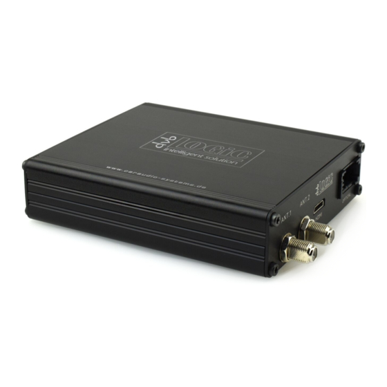
4. Specifications Operation voltage 10.5 – 14.8V DC Stand-by power drain <1mA Operation power drain <1200mA Power consumption <16,5W Temperature range -30°C to +80°C Weight 333g Measurements (box only) B x H x T 140 x 30 x 105 mm 5. Technical Support Caraudio-Systems Vertriebs GmbH manufacturer/distribution In den Fuchslöchern 3 D-67240 Bobenheim-Roxheim email support@caraudio-systems.de Legal disclaimer: Mentioned company and trademarks, as well as product names/codes are registered trademarks ® of their corresponding legal owners. Version 25.09.2017 DT3-CXC-TV1...
Need help?
Do you have a question about the dvbLOGiC DT3-CXC-TV1 and is the answer not in the manual?
Questions and answers