
Related Manuals for Milltronics SL12 Series


Summary of Contents for Milltronics SL12 Series
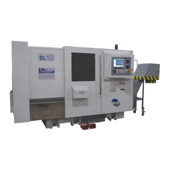
- Page 1 Instruction Handbook for SL12 Lathes Milltronics Manufacturing Company 1400 Mill Lane Waconia, MN 55387 USA Phone 952-442-1410 Fax 952-442-6457 www.milltronics.net Rev 1 1-7-13...
-
Page 3: Table Of Contents
Tool shank size SL12 ....................12 Boring bar size SL6-10....................12 Boring bar size SL12 ....................12 SL12 Series Machine Layout ..................13 Chapter 3 - Site Preparation..................17 Machine Placement Considerations ................17 Power And Ground Requirements ................18 Connecting a Transformer.................. - Page 5 Hydraulic Tailstock and chuck pressure adjustments..........39 Hydraulic Chuck Pressure and Proximity Switches ............ 39 Chapter 7 – 7200 CNC Operation ................. 41 Milltronics 7200 CNC Front Panel ................41 Power ON........................41 Power OFF......................... 41 Diagram of Main Screen..................... 44 C-Axis and Live Tooling Operation (option)..............
-
Page 7: Chapter 1 - Safety
Chapter 1 - Safety The general principles for safe operation of Milltronics machines are outlined in this manual. Every Milltronics machine is engineered for safety. You will note, for example, that all rotating parts are protected by specially designed covers. On some models, the... -
Page 8: Safety Checklist
Safety Checklist • Always observe the safety instructions inscribed on the safety labels fixed onto the machine. Do not remove or alter these labels. • Do not attempt to operate this machine until you have read the manuals supplied with the machine and understand each of the functions and operation methods. •... -
Page 9: Clothing And Personal Safety
• Do not subject the CNC control unit, the operator’s panel, or the electrical control panel to strong voltage fluctuations. • Do not change any machine parameter values without consulting Milltronics service department. If it becomes necessary to change a value, first check if it is safe to do so, then make a note of the original value so it can be reset if necessary. - Page 10 • Do not operate the machine while wearing loose or baggy clothes. • Always completely fasten buttons and hooks on the arms of clothing to avoid danger of entanglement in machine mechanisms. • Do not operate the machine under the influence of drugs or alcohol. •...
-
Page 11: Safety Related To Workpiece Machining And Tooling
1 - S HAPTER AFETY Safety Related to Workpiece Machining And Tooling 1. DANGER • Never operate the spindle above the rated speed of accessories mounted on it (chucks, tooling, etc). • Do not extend stock out of a lathe headstock without an appropriate bar feed or support. -
Page 12: Electrical Safety
Electrical Safety Read and understand the following list of cautions before attempting to perform service on this equipment. Failure to observe these rules can result in death or serious injury. 1. DANGER • Only qualified personnel should attempt to take current and voltage readings or perform service. -
Page 13: Machine Safety Labels
1 - S HAPTER AFETY maintenance, such as cleaning the table or removing chips from the machining enclosure, the machine should be put in an emergency stop condition, de-energizing the axis servo motors and spindle motor. Following these precautions prevents someone from becoming trapped or entangled in the machine. -
Page 14: Safety And Maintenance Label Locations And Descriptions
Safety and Maintenance Label Locations and Descriptions Item Description Page Danger and Safety Precaution Extended Material/Stock Danger Chip Auger/Conveyor Hazard Main Power Hazard and Notice Lathe Safety Operation Instructions Warmup and daily checks Hydraulic Oil Maintenance Notice Waylube maintenance... - Page 15 1 - S HAPTER AFETY Read and understand all Safety, Operation, and Maintenance labels affixed to the machine to ensure safety and reliability. Located at headstock end near spindle through hole. Located around hazard areas on models equipped with chip conveyor.
- Page 16 Located near main power disconnect switch on all models. Located at front of lathe near operator station where it is clearly visible. Important safety guidelines that must be observed. All models, located near operator station. Perform all checks to prevent damage and ensure reliable operation.
-
Page 17: Chapter 2 - Specification
Chapter 2 - Specification Machine Weights SL10 SL12 Lbs. 7000 7000 13,250 2700 2700 6000 Current/Voltage requirements SL10 SL12 STD SL12 OPT Voltage 208-240 VAC 208-240 VAC 208-240 VAC 208-240 VAC Current 50 Amps 60 Amps 60 Amps 100 Amps Transformer 11 KVA 20 KVA... -
Page 18: Tooling Specifications
Tooling Specifications Milltronics SL series lathes come equipped for various tooling sizes depending on machine model and turret size selected. Please refer to your machine order or dealer to find out what tooling is required for your particular machine. Tool shank size SL6-10 The standard 8-position turret uses 1”... -
Page 19: Sl12 Series Machine Layout
2 - S HAPTER PECIFICATION SL12 Series Machine Layout 168” 122” 4” 23” 74” 81”... - Page 20 Item Identification (SL10 shown) Worklight Tool Turret and Tailstock Operator panels Setup/door switch Waylube unit and hydraulic fluid level indicator.
- Page 21 2 - S HAPTER PECIFICATION Hydraulic valves, pressure switches, and gauges Conveyor Chute and chip bucket (option) Leveling bolt and pad Coolant tank with level indicator Coolant pump (facing rear of machine) Spindle, chuck, and parts catcher Main power disconnect switch (Located at rear of machine)
-
Page 23: Chapter 3 - Site Preparation
1. At least 4” thick concrete slab free of cracks and not crossing any expansion joints. Milltronics will not guarantee machine geometry unless this is adhered to. 2. Ample ceiling height, and clearance behind the machine to fully open the door of the electrical cabinet at the rear of the machine. -
Page 24: Power And Ground Requirements
4. Milltronics does not allow the use of a separate grounding rod. 5. Milltronics does not allow conduit or wire raceways be used as a ground. 6. If a transformer is used to step the voltage down to 220 refer to the transformer grounding procedures immediately following this page. -
Page 25: Connecting A Transformer
3 – S HAPTER REPARATION Connecting a Transformer It is important that proper grounding procedures be followed when hooking up machines to power. Please review the following pages. They explain proper transformer connections and checks to ensure proper connections. Refer to the autotransformer diagram provided to verify that your connections are suitable. -
Page 26: Autotransformer Connection Diagram
Autotransformer Connection Diagram If your machine was ordered from Milltronics with a transformer option an autotransformer is supplied. The diagram below illustrates the various input voltage selections and proper ground wire connections. Always call the factory if in doubt concerning transformer connections as serious... -
Page 27: Air Supply System (If Equipped)
HAPTER REPARATION Air Supply System (if equipped) Some Milltronics turning centers require a constant supply of quality air pressure in order to perform optimally. 90-110 PSI at 10 CFM is required. Adjustments • Set the main air regulator to 90 PSI. -
Page 28: Lifting
Lifting The preferred method of lifting Milltronics SL series lathes is by forklift. By Crane or Hoist If a crane or hoist must be used, the machine must be lifted using a special lifting pallet and spreader bar, along with straps rated to handle the weight of the machine (See Chapter 2). -
Page 29: Chapter 4 - Installation
Startup checklist The enclosed startup checklist guides the process of the machine installation and checkout. The startup checklist forms must be completed and sent to Milltronics Mfg. to activate the machine warranty. Use the startup checklist in conjunction with the following outline when installing and setting up the machine. - Page 30 Once the machine is in place and assembled this far, have the power and air supplies connected by qualified personnel as described in chapter 1. See the safety checklist on page 2 for qualifications. Place the leveling block on the tailstock ways as pictured, then rough level the machine.
-
Page 31: Level The Machine
SL Lathe Head Stock Taper Specification (Refer to this text while leveling the machine in the startup checklist) Milltronics SL lathe products have a .0002 inch per foot specification for head stock taper. In almost all cases action will be required at the time of setup to adjust the lathe into tolerance. - Page 32 By inserting a ground bar into the spindle with the chuck removed. This requires a bar that has the morse taper of the spindle ground into its end. Typically there is a spindle taper adapter plug shipped with the machine to be used with a center, and this taper can be used as well.
-
Page 33: Initial Checks Of The Machine, Its Guards And Safety Systems
4 - I HAPTER NSTALLATION Initial Checks of the Machine, its Guards and Safety Systems General Checks 1. Check for missing parts. Do not operate the machine if parts are missing. 2. Visually check for damage outside of machine and inside. Do not operate the machine if there has been shipping damage. -
Page 34: Visually Check That Guards Are In Place
they did. Find qualified personnel (as described in chapter 1) to correct the problems. WARNING: DANGEROUS VOLTAGES EXIST FOR THE VOLTAGE LEVEL CHECKS! 2. Check voltage levels. As stated in the Electrical Safety Rules, only qualified personnel should attempt to take these measurements. With the electrical cabinet door open, turn on the main power at the disconnect switch. -
Page 35: Safety Checks
On Milltronics lathes, the Z axis homes in the center of travel. Turn main power on. Press the green ENABLE button to power up servos. Note: If the machine does not ENABLE, check all emergency stop switches: conveyor, remote hand controller, etc. -
Page 36: Test The Emergency Stop Circuit
Test the Emergency Stop Circuit Having followed the steps outlined above for resetting the machine and starting the spindle, then Press the red EMERGENCY STOP button. Spindle rotation should stop. The emergency stop button is the most important safety switch on the machine. It stops and then de-energizes the spindle motor. (At the same time, it stops and de-energizes the axis servo motors, although they are not running for this test.) When the red emergency stop button is pushed, the spindle should brake to a... -
Page 37: Chapter 5 - Failure Modes, Detection And Prevention
Chapter 5 - Failure Modes, Detection and Prevention Minimizing Wear and Tear • The effects of everyday wear and tear may be minimized by good maintenance practice. Items high on the maintenance list include keeping the machine clean, providing clean dry compressed air with the correct oil drip into the air stream, and continuous application of the correct way oil through the automatic oiler. -
Page 38: Diagnosing Mechanical Faults
Diagnosing Mechanical Faults • Eyes, ears and hands are the best tools for detecting mechanical failure modes. As is the case for electrical faults, an accidental crash between tool and workpiece is a likely way to cause mechanical damage. A wide variety of mechanical failure modes also are possible even without a crash. -
Page 39: Chapter 6 - Maintenance
Chapter 6 – Maintenance Periodic Maintenance; Verification Of Safety Systems Note: Before performing any of the procedures in this section, please read and follow the directions in this manual covering safe practices for operation, setting and maintenance. Maintenance operations should only be performed by qualified personnel as described in chapter 1. -
Page 40: Monthly
• Inspect the coolant collector at the rear of the spindle to ensure it is draining properly and is not blocked by chips. If cutting chips accumulate in the collector, install a plug in the spindle/chuck bore to prevent this. – Also see “hydraulic chuck”... -
Page 41: Safety Checks, To Be Carried Out Monthly And After Maintenance Operations
6 - M HAPTER AINTENANCE • Change turret gear oil. Safety Checks, to be carried out monthly and after maintenance operations • Repeat the checks for correct operation of the emergency stop circuit and of the safety enclosure circuit outlined in Chapter 4 of this manual. •... -
Page 42: Air System Maintenance (If Equipped)
Air System Maintenance (if equipped) • Ensure the air lubrication unit dispenses oil, and that the oil reservoir fill level is maintained. (Use Marvel No. 085, Mobil Velocite No. 10 or equivalent oil, further details about lubrication type can be found in the mechanical manual) •... -
Page 43: Way Lube Maintenance
6 - M HAPTER AINTENANCE Way Lube Maintenance • Ensure the way lube reservoir level is maintained (if equipped). (Use Mobil Vactra No. 02, Amoco Waytec No 68, Sunoco Sunwaylube No1180, or equivalent oil, further details about this lubricant can be found in the mechanical manual). -
Page 44: Tool Turret Maintenance - Pragati (If Equipped)
Tool Turret Maintenance – LS-200 (if equipped) Monitor sight glass to ensure fluid level remains topped off. Lubrication is supplied by hydraulic system. See LS-200 turret manual if troubleshooting information is required. Hydraulic System Maintenance Check oil level in the hydraulic tank weekly and top off with Mobil DTE24 or equivalent if necessary. -
Page 45: Hydraulic Tailstock And Chuck Pressure Adjustments
6 - M HAPTER AINTENANCE Hydraulic Tailstock and chuck pressure adjustments Adjust pressure to suit requirements of the operation Pressure adjustments Hydraulic Chuck Pressure and Proximity Switches The hydraulic pressure switches are located behind the left hinged side panel of the machine. -
Page 47: Chapter 7 - 7200 Cnc Operation
Chapter 7 – 7200 CNC Operation Milltronics 7200 CNC Front Panel 3 4 5 ower ON The main po wer switch is located on the electrical cabinet at the back of the machine. When main power is switched on, the power to the CNC is also applied. - Page 48 1) Manua l Pulse Generator (HANDWHEEL) - rotate this wheel to control axis feed while in HDW mode. 2) FEEDRATE override rotary switch - labeled in percentages. Controls the feedrate and rapid t raverse (Exception - see #3) of the machine axes. Also affects handwheel rate.
- Page 49 7 – 7200 CNC O HAPTER PERATION o Spindle CCW button – starts spindle in counter-clockwise direction provided there is a programmed spindle rpm. o Spindle STOP button – stops spindle rotation. 9) EMERGENCY STOP button – Disables machine motion, control enable, and axis waylube oiler.
-
Page 50: Diagram Of Main Screen
Diagram of Main Screen RunTime When you are verifying a program the runtime displays the calculated time to make the parts. When you are running a program it shows the elapsed time since the program was started. The total of all program run times are kept in the “Job Time”... - Page 51 7 – 7200 CNC O HAPTER PERATION The Function Keys Highlighted Function Keys are active or available. Status Window Status Window displays detailed information on the state of the control. A detailed description is given below. Diagram of Status Window The \ changes back and forth to / and \ each time the status window is updated.
- Page 52 Spindle: The program med revolutions per minute. Spindle override and direction: The position of the s pindle override and the resulting rpm (if th ere is no spindle encoder) or the actual rpm (if there is a spindle encoder). This line also displays whether the spindle is off or runnin g CW or CCW.
-
Page 53: C-Axis And Live Tooling Operation (Option)
7 – 7200 CNC O HAPTER PERATION C-Axis and Live Tooling Operation (option) indle Selection Commands G24, G25 G24 - Select main spindle G25 - Sele ct live tooling spindle r power up, a spindle must be selected before executing any other spindle mands. - Page 54 Spindle Jog Function The spindle jog button (when the door is open) will jog the main spindle (if in G24). If in G25 (live tooling spindle) the j og button (when the door is open) will jog the live tooling spindle. illing/Tapping Notes is possible to drill (or tap) 3 different ways.
-
Page 55: Chapter 8 Parts Lists And Drawings
8 – P HAPTER ARTS ISTS AND RAWINGS Chapter 8 Parts Lists and Drawings Chapter 8 Parts Li sts and Drawings ................Hydra ulic Chuck ......................50 Spindl e Transmission System ..................52 Spindl e Speed Detector ..................... - Page 57 HAPTER ARTS ISTS AND RAWINGS Parts List for Hydraulic Chuck Item Part no. Description Q'ty Remark Milltronics # 3-jaw chuck (92HT) NB-212A8 E-ARFD-80001-01 Pull tube (92HT) E-ARFC-00001-01 Head stock (76/92HT) E-ARFC-07003-01 Washer 5001-A16200070 Hex. socket screw M16XP2.0X70L E-ARFC-00002-01 Fixing block 5001-A12175050 Hex.
-
Page 58: Spindle Transmission System
Spindle Transmission System... - Page 59 8 – P HAPTER ARTS ISTS AND RAWINGS Parts list for spindle transmission system Milltronics # Item P art n Descrip tion 'ty R 5001-A06100025 ex. socket screw M6 X P1.0 X 25L -ARFC-07005-01 over (76/92HT) -ARFC-07004-01 pacer (76/92HT) Ring (76HT/92HT)
-
Page 60: Spindle Speed Detector
Spindle Speed Detector... - Page 61 8 – P HAPTER ARTS ISTS AND RAWINGS Parts list for spindle speed detector Mill tronics # Item Part no. Descr iption Q'ty Rema F ixing nut AN-02 ixing washer W-02 E-ARAK-03023-01 iming belt pulley iming belt 1050-5M 15 BT-104 E-ARAK-03002-01 ncoder bracket 5121-C05005020...
-
Page 62: Headstock (C-Axis Option)
Headstock (C-axis option) - Page 63 8 – P HAPTER ARTS ISTS AND RAWINGS Parts list for Headstock (C-axis option) Item Part no. cription Q'ty Milltronics # 5001-A08125050 Hex. socket screw 8XP1.2 5X50L E-ARFC-55001-01 Bracket (76/92 5001-A12175050 Hex. sock et screw 12XP1.75X50L Hydraulic braking unit DB-2021B...
-
Page 64: Parts Catcher (Option)
Parts Catcher (option) - Page 65 8 – P HAPTER ARTS ISTS AND RAWINGS Parts list for parts catcher (option) Item Part no. Description Q'ty Remark Milltronics # 8XP1.25 E-ARFC-85022- 1 Fixing plate E-ARFC-85005-01 Shaft Air-cylinder SF40X90SD 5001- 08125065 Hex. socket screw 8XP1.25X6 5001- 08125025 Hex. soc ket screw M8XP .25X25L...
-
Page 66: Cut Off Detector (Option)
Cut off Detector (option) - Page 67 8 – P HAPTER ARTS ISTS AND RAWINGS Parts list for cut off detector (option) Item Part no. Description Q'ty Remark Milltronics # M6XP 5001-A06100020 Hex. socket screw 6XP1.0X20 E-ARFC-85001-01 ixing plate E-ARFC-85015-01 Fixing plate 5001-A06100065 Hex. socket screw M 6XP1.0X65L 5001-A08125025 ex.
-
Page 68: X-Axis
X-Axis... - Page 69 8 – P HAPTER ARTS ISTS AND RAWINGS Parts list for X-axis Item Part no. Description Q'ty Remark Milltronics # E-ARF C-30013-01 Fixing plate E- RF C-30009-01 Wipe 5001-A10150055 . sock et screw 1.5X55L -ARFC-30001-01 C ss slide -ARFC-30010-01 Wi er...
-
Page 70: Z-Axis
Z-Axis... - Page 71 8 – P HAPTER ARTS ISTS AND RAWINGS Parts list for Z-axis Item Part no. Description Milltroni cs # Servo motor Sigma2 4.4kw MO-129 5001-A12175040 Hex. socket screw M12XP1.75X Spring washer Coupling 32/35 YSF-M35XP1.5 MPL-427 E-ARFC-53005-01 Spacer 5001-A06100016 Hex. socket screw M6XP1.0X16L E-ARFC-53004-01 Cover...
-
Page 72: Tailstock
Tailstoc Not shown: Tailstock limit switch BNS0003, SW-200... - Page 73 8 – P HAPTER ARTS ISTS AND RAWINGS Parts list for tailstock Item Part no. Descripti Remark Milltronics -snap TW-40 0° connector PT3/8" 5001-A06100035 Hex. socket screw 6XP1. 0X35L E-ARFC-60 010-01 Rear cover O ring G-100 RFC-60008-01 Bar ring 5001-A05080016 Hex.
- Page 74 Item Part no. Description Q'ty Remark Milltronics # E-ARFC-60003-01 Riser plate E-ARFC-60005-01 Gib E-ARAK-20010-01 Adjusting screw U ring DKI-30X42X6 E-ARFC-60031-01 Fixing block 5001-A12175030 Hex. socket screw M12XP1.75X30L 5001-A06100020 Hex. socket screw M6XP1.0X20L E-ARFC-60026-01 Cylinder cover O ring G-50 O ring...
- Page 75 8 – P HAPTER ARTS ISTS AND RAWINGS This page inte ntio unused...
-
Page 76: Guarding
Guarding... - Page 77 8 – P HAPTER ARTS ISTS AND RAWINGS Parts list for Guarding Item Part Description Q'ty Remark E-ARFC-70041-01 Cover E-ARFC-70040-01 Side door cover E-ARFC-70039-01 Spindle guard E-ARFC-70037-01 Left guard E-ARFC-70038-01 Plate E-ARFC-70030-01 Plate E-ARFC-70029-01 Left bracket E-ARFC-70050-01 Side guard E-ARFC-70049-01 Left guard E-ARFC-70062-01 Cover E-ARFC-70036-01 Side bracket E-ARFC-70016-01 Top bracket...
-
Page 78: Guarding - Door
Guarding - Door... - Page 79 8 – P HAPTER ARTS ISTS AND RAWINGS Parts List for Guarding - Door Item Part scription Q'ty e ark Guide way Sliding block E-ARFC-70017-01 Bracket E-ARFC-70044-01 Front door E-ARFC-70043-01 Clamp plate Parts cabinet ptio ) Revolving shaft E-ARFC-70032-01 Control panel E-ARFC-70033-01 Plate E-ARFC-70019-01...
-
Page 80: Guarding (Electrical Box)
Guarding (Electrical Box) - Page 81 8 – P HAPTER ARTS ISTS AND RAWINGS Parts List for guarding (electrical box) Item Part no. Description Q'ty Remark E-ARF C-70003- ght door E-ARFC-70002-01 eft door E-ARFC-70006-01 racket-main d isconn ect switch Electrical panel lectrical pa E-ARFC-70004-01 late E-ARFC-70001-01 abinet E-ARFC-70009-01 racket...
-
Page 82: Air Frl And Parts Catcher Solenoid
Air FRL and Parts Catcher Solenoid NU-335 Cap only NU-535 Bowl only NU-477 NU-322... -
Page 85: Startup Checklist For Sl Series Lathes
Checked By Air ran to machine if required (90 to 120 psi), 10 CFM Checked By Milltronics Representative Responsibility (Initial or write n/a if does not apply) Check for missing parts Visually check for damage outside of machine and inside. - Page 87 Make sure the machine is wired to the GND line from the plant AC distribution system by a copper wire equal to or grea ter in size than the power feed wires. Milltronics does not allow the use of a separate ground rod, conduit, or wire raceways to be used as a ground source.
- Page 89 ACONIA : 952.442.6455 • F : 952.442.6457 www.milltronics.net RESET MACHINE AND BE READY TO E-STOP IN CASE OF AXIS RUNAWAY. Home the machine (machine must be in RESET). Check for smooth motion. Check the flood pump rotation and verify lubricator function.
- Page 91 • W • MN 55387 1400 M ACONIA : 952.442.6455 • F : 952.442.6457 www.milltronics.net Turret MDI - tool change tool # 1 (M6 T0101) Check the turret position Hydraulic chuck (optional) Clamp and unclamp by use of foot switch Check I.D.
- Page 93 I / we accept this machine, its installation, and the terms of the warranty. Customer Signature Print Date Milltronics Rep. Print Date When this form is complete forward it to Milltronics for warranty activation commencing on the date of initial delivery to the first customer.
Need help?
Do you have a question about the SL12 Series and is the answer not in the manual?
Questions and answers