
Related Manuals for Milltronics SL12 Series


Summary of Contents for Milltronics SL12 Series
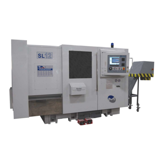
- Page 1 Instruction Handbook for SL12 Lathes Milltronics Manufacturing Company 1400 Mill Lane Waconia, MN 55387 USA Phone 952-442-1410 Fax 952-442-6457 www.milltronics.net Rev 1 10-2-2013...
-
Page 3: Table Of Contents
Control Instructions, Schematics, and Mechanical Parts list ........11 Tooling Specifications ....................12 Tool shank size SL12 ....................12 Boring bar size SL12 ....................12 SL12 Series Machine Layout ..................13 Chapter 3 - Site Preparation..................17 Machine Placement Considerations ................17 Power And Ground Requirements................18 Connecting a Transformer.................. - Page 5 Hydraulic System Maintenance.................. 38 Hydraulic Tailstock and chuck pressure adjustments..........39 Hydraulic Chuck Pressure and Proximity Switches ............ 39 Chapter 7 – 8200 CNC Operation ................. 41 Milltronics 8200 CNC Front Panel ................41 Power ON........................41 Power OFF ......................... 41...
-
Page 7: Chapter 1 - Safety
Chapter 1 - Safety The general principles for safe operation of Milltronics machines are outlined in this manual. Every Milltronics machine is engineered for safety. You will note, for example, that all rotating parts are protected by specially designed covers. On some models, the... -
Page 8: Safety Checklist
Safety Checklist • Always observe the safety instructions inscribed on the safety labels fixed onto the machine. Do not remove or alter these labels. • Do not attempt to operate this machine until you have read the manuals supplied with the machine and understand each of the functions and operation methods. •... -
Page 9: Clothing And Personal Safety
• Do not subject the CNC control unit, the operator’s panel, or the electrical control panel to strong voltage fluctuations. • Do not change any machine parameter values without consulting Milltronics service department. If it becomes necessary to change a value, first check if it is safe to do so, then make a note of the original value so it can be reset if necessary. - Page 10 • Always completely fasten buttons and hooks on the arms of clothing to avoid danger of entanglement in machine mechanisms. • Do not operate the machine under the influence of drugs or alcohol. • If wearing gloves to load or unload parts, be sure the machine is in emergency stop mode.
-
Page 11: Safety Related To Workpiece Machining And Tooling
1 - S HAPTER AFETY Safety Related to Workpiece Machining And Tooling 1. DANGER • Never operate the spindle above the rated speed of accessories mounted on it (chucks, tooling, etc). • Do not extend stock out of a lathe headstock without an appropriate bar feed or support. -
Page 12: Electrical Safety
• Ensure all hardware is tight and properly tightened after performing maintenance operations. Electrical Safety Read and understand the following list of cautions before attempting to perform service on this equipment. Failure to observe these rules can result in death or serious injury. -
Page 13: Machine Safety Labels
1 - S HAPTER AFETY performed on a machine under power. For even the most routine day-to-day maintenance, such as cleaning the table or removing chips from the machining enclosure, the machine should be put in an emergency stop condition, de-energizing the axis servo motors and spindle motor. -
Page 14: Safety And Maintenance Label Locations And Descriptions
Safety and Maintenance Label Locations and Descriptions Item Description Page Danger and Safety Precaution Extended Material/Stock Danger Chip Auger/Conveyor Hazard Main Power Hazard and Notice Lathe Safety Operation Instructions Warmup and daily checks Hydraulic Oil Maintenance Notice Waylube maintenance... - Page 15 1 - S HAPTER AFETY Read and understand all Safety, Operation, and Maintenance labels affixed to the machine to ensure safety and reliability. Located at headstock end near spindle through hole. Located around hazard areas on models equipped with chip conveyor.
- Page 16 Located near main power disconnect switch on all models. Located at front of lathe near operator station where it is clearly visible. Important safety guidelines that must be observed. All models, located near operator station. Perform all checks to prevent damage and ensure reliable operation.
-
Page 17: Chapter 2 - Specification
Chapter 2 - Specification Basic Machine Specifications Machine Model SL12 CAPACITY Swing Over Way Cover 30" 760 mm Swing Over Carriage 23" 600 Bar Capacity, Diameter 3.58" 91 mm Chuck Size 12" 305 mm Machine Weight 13,250 lb 6000 kg Extended Bed Machine Weight 18,750 lb 8500 kg... -
Page 18: Tooling Specifications
Tooling Specifications Milltronics SL series lathes come equipped for various tooling sizes depending on machine model and turret size selected. Please refer to your machine order or dealer to find out what tooling is required for your particular machine. -
Page 19: Sl12 Series Machine Layout
2 - S HAPTER PECIFICATION SL12 Series Machine Layout 168” 122” 4” 74” 23” 81”... - Page 20 Item Identification (SL10 shown) Worklight Tool Turret and Tailstock Operator panels Setup/door switch Waylube unit and hydraulic fluid level indicator.
- Page 21 2 - S HAPTER PECIFICATION Hydraulic valves, pressure switches, and gauges Conveyor Chute and chip bucket (option) Leveling bolt and pad Coolant tank with level indicator Coolant pump (facing rear of machine) Spindle, chuck, and parts catcher Main power disconnect switch (Located at rear of machine)
-
Page 23: Chapter 3 - Site Preparation
1. At least 4” thick concrete slab free of cracks and not crossing any expansion joints. Milltronics will not guarantee machine geometry unless this is adhered to. 2. Ample ceiling height, and clearance behind the machine to fully open the door of the electrical cabinet at the rear of the machine. -
Page 24: Power And Ground Requirements
4. Milltronics does not allow the use of a separate grounding rod. 5. Milltronics does not allow conduit or wire raceways be used as a ground. 6. If a transformer is used to step the voltage down to 220 refer to the transformer grounding procedures immediately following this page. -
Page 25: Connecting A Transformer
3 – S HAPTER REPARATION Connecting a Transformer It is important that proper grounding procedures be followed when hooking up machines to power. Please review the following pages. They explain proper transformer connections and checks to ensure proper connections. Refer to the autotransformer diagram provided to verify that your connections are suitable. -
Page 26: Autotransformer Connection Diagram
Autotransformer Connection Diagram If your machine was ordered from Milltronics with a transformer option an autotransformer is supplied. The diagram below illustrates the various input voltage selections and proper ground wire connections. Always call the factory if in doubt concerning transformer connections as serious... -
Page 27: Air Supply System (If Equipped)
HAPTER REPARATION Air Supply System (if equipped) Some Milltronics turning centers require a constant supply of quality air pressure in order to perform optimally. 90-110 PSI at 10 CFM is required. Adjustments • Set the main air regulator to 90 PSI. -
Page 28: Lifting
Lifting The preferred method of lifting Milltronics SL series lathes is by forklift. By Crane or Hoist If a crane or hoist must be used, the machine must be lifted using a special lifting pallet and spreader bar, along with straps rated to handle the weight of the machine (See Chapter 2). -
Page 29: Chapter 4 - Installation
Startup checklist The enclosed startup checklist guides the process of the machine installation and checkout. The startup checklist forms must be completed and sent to Milltronics Mfg. to activate the machine warranty. Use the startup checklist in conjunction with the following outline when installing and setting up the machine. -
Page 30: Level The Machine
Once the machine is in place and assembled this far, have the power and air supplies connected by qualified personnel as described in chapter 1. See the safety checklist on page 2 for qualifications. Place the leveling block on the tailstock ways as pictured, then rough level the machine. -
Page 31: Lathe Head Stock Taper Specification
SL Lathe Head Stock Taper Specification (Refer to this text while leveling the machine in the startup checklist) Milltronics SL lathe products have a .0002 inch per foot specification for head stock taper. In almost all cases action will be required at the time of setup to adjust the lathe into tolerance. -
Page 32: Initial Checks Of The Machine, Its Guards And Safety Systems
Initial Checks of the Machine, its Guards and Safety Systems General Checks 1. Check for missing parts. Do not operate the machine if parts are missing. 2. Visually check for damage outside of machine and inside. Do not operate the machine if there has been shipping damage. -
Page 33: Visually Check That Guards Are In Place
4 - I HAPTER NSTALLATION WARNING: DANGEROUS VOLTAGES EXIST FOR THE VOLTAGE LEVEL CHECKS! 2. Check voltage levels. As stated in the Electrical Safety Rules, only qualified personnel should attempt to take these measurements. With the electrical cabinet door open, turn on the main power at the disconnect switch. Do not reset the drives, i.e. -
Page 34: Safety Checks
On Milltronics lathes, the Z axis homes in the center of travel. Turn main power on. Press the green ENABLE button to power up servos. Note: If the machine does not ENABLE, check all emergency stop switches: conveyor, remote hand controller, etc. -
Page 35: Test The Emergency Stop Circuit
4 - I HAPTER NSTALLATION Test the Emergency Stop Circuit Having followed the steps outlined above for resetting the machine and starting the spindle, then Press the red EMERGENCY STOP button. Spindle rotation should stop. The emergency stop button is the most important safety switch on the machine. -
Page 37: Chapter 5 - Failure Modes, Detection And Prevention
Chapter 5 - Failure Modes, Detection and Prevention Minimizing Wear and Tear • The effects of everyday wear and tear may be minimized by good maintenance practice. Items high on the maintenance list include keeping the machine clean, providing clean dry compressed air with the correct oil drip into the air stream, and continuous application of the correct way oil through the automatic oiler. -
Page 38: Diagnosing Mechanical Faults
Diagnosing Mechanical Faults • Eyes, ears and hands are the best tools for detecting mechanical failure modes. As is the case for electrical faults, an accidental crash between tool and workpiece is a likely way to cause mechanical damage. A wide variety of mechanical failure modes also are possible even without a crash. -
Page 39: Chapter 6 - Maintenance
Chapter 6 – Maintenance Periodic Maintenance; Verification Of Safety Systems Note: Before performing any of the procedures in this section, please read and follow the directions in this manual covering safe practices for operation, setting and maintenance. Maintenance operations should only be performed by qualified personnel as described in chapter 1. -
Page 40: Weekly
Weekly • Check operation of all cooling fans. • Clean any chips from around the tool turret. • Inspect the coolant collector at the rear of the spindle to ensure it is draining properly and is not blocked by chips. If cutting chips accumulate in the collector, install a plug in the spindle/chuck bore to prevent this. -
Page 41: Annually
6 - M HAPTER AINTENANCE Annually • Check backlash to ensure proper axis motion and response. • Check taper. Machine settling can affect machine geometry. • Clean the intake screen on the way lube pump. • Change hydraulic oil. • Change turret gear oil. Safety Checks, to be carried out monthly and after maintenance operations •... -
Page 42: Air System Maintenance (If Equipped)
Air System Maintenance (if equipped) • Ensure the air lubrication unit dispenses oil, and that the oil reservoir fill level is maintained. (Use Marvel No. 085, Mobil Velocite No. 10 or equivalent oil, further details about lubrication type can be found in the mechanical manual) •... -
Page 43: Way Lube Maintenance
6 - M HAPTER AINTENANCE Way Lube Maintenance • Ensure the way lube reservoir level is maintained (if equipped). (Use Mobil Vactra No. 02, Amoco Waytec No 68, Sunoco Sunwaylube No1180, or equivalent oil, more details found in mechanical manual). •... -
Page 44: Tool Turret Maintenance - Ls-200 (If Equipped)
Tool Turret Maintenance – LS-200 (if equipped) Monitor sight glass to ensure fluid level remains topped off. Lubrication is supplied by hydraulic system. See LS-200 turret manual if troubleshooting Site Glass information is required. Hydraulic System Maintenance Check oil level in the hydraulic tank weekly and top off with Mobil DTE24 or equivalent if necessary. -
Page 45: Hydraulic Tailstock And Chuck Pressure Adjustments
6 - M HAPTER AINTENANCE Hydraulic Tailstock and chuck pressure adjustments Adjust pressure to suit requirements of the operation Pressure adjustments Hydraulic Chuck Pressure and Proximity Switches The hydraulic pressure switches are located behind the left hinged side panel of the machine. -
Page 47: Chapter 7 - 8200 Cnc Operation
Chapter 7 – 8200 CNC Operation Milltronics 8200 CNC Front Panel 3 4 5 Power ON The main power switch is located on the electrical cabinet at the back of the machine. When main power is switched on, the power to the CNC is also applied. - Page 48 1) Manual Pulse Generator (HANDWHEEL) - rotate this wheel to control axis feed while in HDW mode. 2) FEEDRATE override rotary switch - labeled in percentages. Controls the feedrate and rapid traverse (Exception - see #3) of the machine axes. Also affects handwheel rate.
- Page 49 7 – 8200 CNC O HAPTER PERATION 8) SPINDLE CW/STOP/CCW o Spindle CW button – starts spindle in clockwise direction provided there is a programmed spindle rpm. o Spindle CCW button – starts spindle in counter-clockwise direction provided there is a programmed spindle rpm. o Spindle STOP button –...
Need help?
Do you have a question about the SL12 Series and is the answer not in the manual?
Questions and answers